Week 14. networking and communication
Assignment
- group project: send a message between two projects
- individual assignment: design and build a wired &/or wireless network connecting at least two processors
group assignment
see FabLab Kamakura's group assignment page.
introduction
As we learned last class, a lot of options for interface two components. In my final project, surFABoard will have GPS module, temperature sensors, and SD card logger at least as shown below.

When I want to add more sensors to a board, I think sensors with I2C interface would be a better choice than others, because the I2C protocol uses only two wires to communicate with other sensors(up to 128 devices).
As preparation for my final project, I chose I2C interface in this week assignment.

assignment
board preparation
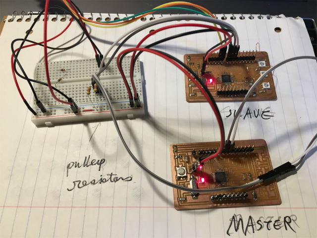
I redraw a satshakit and added LEDs in week 12 which I used as a slave. I made another one, which I used as a master, to connect and communicate with them via I2C. I also wired pullup resistors both SCL and SDA line.

master writer/slave receiver
First, I tested a Master Writer/Slave Receiver sketch. Sketches for master and slave are followings.
master sketch
// Wire Master Writer
// by Nicholas Zambetti

// Demonstrates use of the Wire library
// Writes data to an I2C/TWI slave device
// Refer to the "Wire Slave Receiver" example for use with this

// Created 29 March 2006

// This example code is in the public domain.


#include <Wire.h>

void setup() {
  Wire.begin(); // join i2c bus (address optional for master)
}

byte x = 0;

void loop() {
  Wire.beginTransmission(8); // transmit to device #8
  Wire.write("x is ");        // sends five bytes
  Wire.write(x);              // sends one byte
  Wire.endTransmission();    // stop transmitting

  x++;
  delay(500);
}
slave sketch
// Wire Slave Receiver
// by Nicholas Zambetti

// Demonstrates use of the Wire library
// Receives data as an I2C/TWI slave device
// Refer to the "Wire Master Writer" example for use with this

// Created 29 March 2006

// This example code is in the public domain.


#include <Wire.h>

void setup() {
  Wire.begin(8);                // join i2c bus with address #8
  Wire.onReceive(receiveEvent); // register event
  Serial.begin(9600);           // start serial for output
}

void loop() {
  delay(100);
}

// function that executes whenever data is received from master
// this function is registered as an event, see setup()
void receiveEvent(int howMany) {
  while (1 < Wire.available()) { // loop through all but the last
    char c = Wire.read(); // receive byte as a character
    Serial.print(c);         // print the character
  }
  int x = Wire.read();    // receive byte as an integer
  Serial.println(x);         // print the integer
}
After uploading sketches to master and slave, I monitored slave's serial monitor. I found Data send by master was received by slave properly.
master reader/slave sender
Second, I also tested Master Reader/Slave Sender sketch. Sketches are followings.
master sketch
// Wire Master Reader
// by Nicholas Zambetti

// Demonstrates use of the Wire library
// Reads data from an I2C/TWI slave device
// Refer to the "Wire Slave Sender" example for use with this

// Created 29 March 2006

// This example code is in the public domain.


#include <Wire.h>

void setup() {
  Wire.begin();        // join i2c bus (address optional for master)
  Serial.begin(9600);  // start serial for output
}

void loop() {
  Wire.requestFrom(8, 6);    // request 6 bytes from slave device #8

  while (Wire.available()) { // slave may send less than requested
    char c = Wire.read(); // receive a byte as character
    Serial.print(c);         // print the character
  }

  delay(500);
}
slave sketch
// Wire Slave Sender
// by Nicholas Zambetti

// Demonstrates use of the Wire library
// Sends data as an I2C/TWI slave device
// Refer to the "Wire Master Reader" example for use with this

// Created 29 March 2006

// This example code is in the public domain.


#include <Wire.h>
void setup() {
  Wire.begin(8);                // join i2c bus with address #8
  Wire.onRequest(requestEvent); // register event
}

void loop() {
  delay(100);
}

// function that executes whenever data is requested by master
// this function is registered as an event, see setup()
void requestEvent() {
  Wire.write("hello "); // respond with message of 6 bytes
  // as expected by master
}
This time, I monitored a master device's serial monitor, and I found that master recieved a message from a slave.
I2C communication and LED blinking
I modified master writer/slave receiver sketch to blink various colors depending on the result of x modulo 10.

problem
LEDs didn't blink at all. I checked my Eagle design and found that I assigned both I2C SLC and LED's data line to same pin(PIN 19).

I cut the LED's data line and connected to PIN 14(A0).

Here is hero shot in this week.