Week 11. input devices
Assignment
- group project: measure the analog levels and digital signals in an input device
- measure something: add a sensor to a microcontroller board that you have designed and read it.
group assignment
see FabLab Kamakura's group assignment page.
temperature sensor via SPI interface
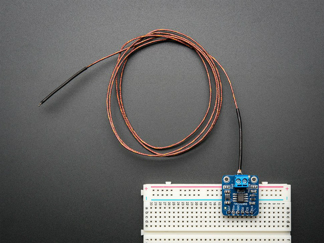
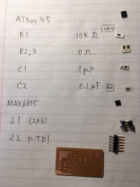
I need a temperature sensor with my surFABoard to measure seawater temperature. Neil's example was one for ambient temperature and not suitable for my purpose. So, I decided to use K-type thermocouple converter, MAX6675 (and MAX31855, eventually).
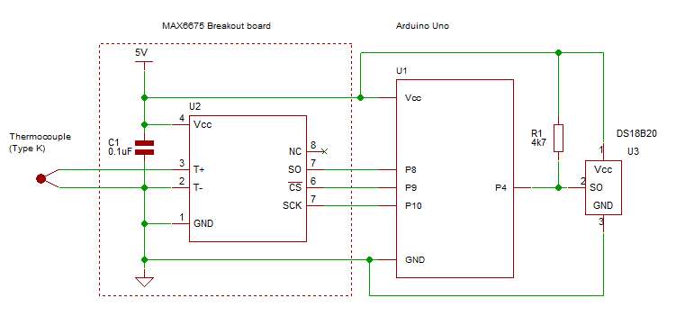
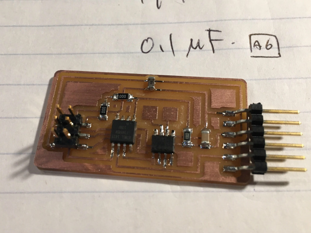
I tried to design a knockoff MAX6675 module and combine it with ATtiny45 with reference to this circuit.
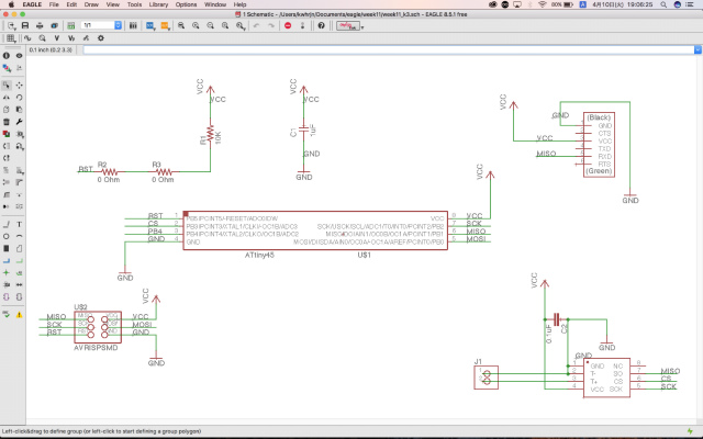
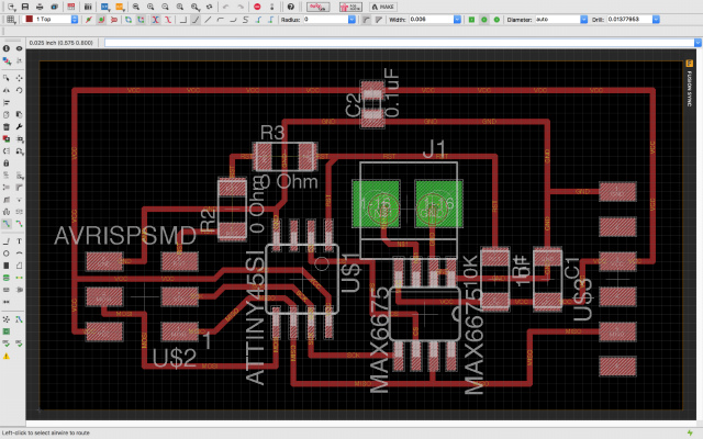
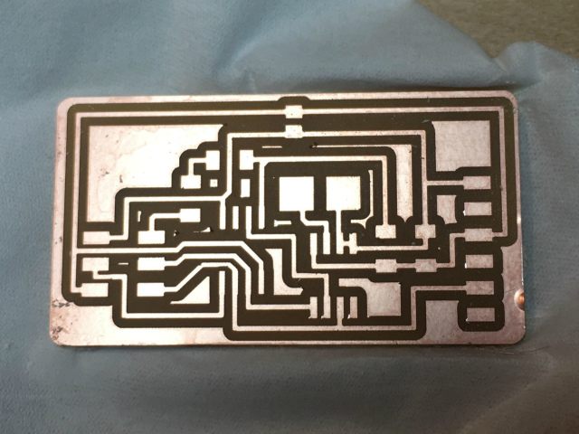
board design/production
MAX6675 connects with a microprocessor through SPI interface. As I couldn't find an example for SPI interface in Fab Academy archive, I designed it with reference to a MAX6675 breakout board.
Eagle schematic/PCB layout and toolpathes for traces/interior: archived format (.zip)
making my board Arduino compatible
problem#1: burning bootloading error
I want to use my board as an Arduino compatible. I tried to burn bootloader, but I've got an error message saying...
Arduino: 1.8.5 (Mac OS X), Board: "ATtiny25/45/85, ATtiny45, Internal 8 MHz"

/Applications/Arduino.app/Contents/Java/hardware/tools/avr/bin/avrdude -C/Applications/Arduino.app/Contents/Java/hardware/tools/avr/etc/avrdude.conf -v -v -v -v -pattiny45 -cusbtiny -e -Uefuse:w:0xff:m -Uhfuse:w:0xdf:m -Ulfuse:w:0xe2:m

avrdude: Version 6.3, compiled on Jan 17 2017 at 12:01:35
         Copyright (c) 2000-2005 Brian Dean, http://www.bdmicro.com/
         Copyright (c) 2007-2014 Joerg Wunsch

         System wide configuration file is "/Applications/Arduino.app/Contents/Java/hardware/tools/avr/etc/avrdude.conf"
         User configuration file is "/Users/kwhrjn/.avrduderc"
         User configuration file does not exist or is not a regular file, skipping

         Using Port                    : usb
         Using Programmer              : usbtiny
avrdude: usbdev_open(): Found USBtinyISP, bus:device: 020:045
         AVR Part                      : ATtiny45
         Chip Erase delay              : 4500 us
         PAGEL                         : P00
         BS2                           : P00
         RESET disposition             : possible i/o
         RETRY pulse                   : SCK
         serial program mode           : yes
         parallel program mode         : yes
         Timeout                       : 200
         StabDelay                     : 100
         CmdexeDelay                   : 25
         SyncLoops                     : 32
         ByteDelay                     : 0
         PollIndex                     : 3
         PollValue                     : 0x53
         Memory Detail                 :

                                  Block Poll               Page                       Polled
           Memory Type Mode Delay Size  Indx Paged  Size   Size #Pages MinW  MaxW   ReadBack
           ----------- ---- ----- ----- ---- ------ ------ ---- ------ ----- ----- ---------
           eeprom        65     6     4    0 no        256    4      0  4000  4500 0xff 0xff
                                  Block Poll               Page                       Polled
           Memory Type Mode Delay Size  Indx Paged  Size   Size #Pages MinW  MaxW   ReadBack
           ----------- ---- ----- ----- ---- ------ ------ ---- ------ ----- ----- ---------
           flash         65     6    32    0 yes      4096   64     64  4500  4500 0xff 0xff
                                  Block Poll               Page                       Polled
           Memory Type Mode Delay Size  Indx Paged  Size   Size #Pages MinW  MaxW   ReadBack
           ----------- ---- ----- ----- ---- ------ ------ ---- ------ ----- ----- ---------
           signature      0     0     0    0 no          3    0      0     0     0 0x00 0x00
                                  Block Poll               Page                       Polled
           Memory Type Mode Delay Size  Indx Paged  Size   Size #Pages MinW  MaxW   ReadBack
           ----------- ---- ----- ----- ---- ------ ------ ---- ------ ----- ----- ---------
           lock           0     0     0    0 no          1    0      0  9000  9000 0x00 0x00
                                  Block Poll               Page                       Polled
           Memory Type Mode Delay Size  Indx Paged  Size   Size #Pages MinW  MaxW   ReadBack
           ----------- ---- ----- ----- ---- ------ ------ ---- ------ ----- ----- ---------
           lfuse          0     0     0    0 no          1    0      0  9000  9000 0x00 0x00
                                  Block Poll               Page                       Polled
           Memory Type Mode Delay Size  Indx Paged  Size   Size #Pages MinW  MaxW   ReadBack
           ----------- ---- ----- ----- ---- ------ ------ ---- ------ ----- ----- ---------
           hfuse          0     0     0    0 no          1    0      0  9000  9000 0x00 0x00
                                  Block Poll               Page                       Polled
           Memory Type Mode Delay Size  Indx Paged  Size   Size #Pages MinW  MaxW   ReadBack
           ----------- ---- ----- ----- ---- ------ ------ ---- ------ ----- ----- ---------
           efuse          0     0     0    0 no          1    0      0  9000  9000 0x00 0x00
                                  Block Poll               Page                       Polled
           Memory Type Mode Delay Size  Indx Paged  Size   Size #Pages MinW  MaxW   ReadBack
           ----------- ---- ----- ----- ---- ------ ------ ---- ------ ----- ----- ---------
           calibration    0     0     0    0 no          1    0      0     0     0 0x00 0x00

         Programmer Type : USBtiny
         Description     : USBtiny simple USB programmer, http://www.ladyada.net/make/usbtinyisp/
avrdude: programmer operation not supported

avrdude: Using SCK period of 10 usec
CMD: [ac 53 00 00] [ff ff ff ff]
CMD: [ac 53 00 00] [ff ff ff ff]
avrdude: initialization failed, rc=-1
         Double check connections and try again, or use -F to override
         this check.


avrdude done.  Thank you.

Error while burning bootloader.
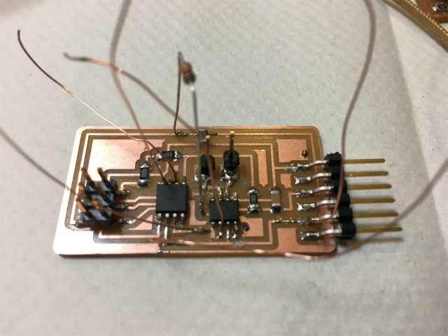
Yamamoto-san, a FabLab Kamakura's electronics GURU, said that a CS (Chip Select) pin should be pulled up with a resistor. Otherwise, the pin would be floating state, which might cause the bootloading error.
After I soldered a 10K pull-up resistor as he said, I could burn bootloader.
arduino sketch
problem#2: Chip Select pin remaining HIGH
I used a MAX6675 library and modified an example sketch to use serial monitor.
After loading my sketch, temperature sensor reading was 0 degree in Celsius, which meant it's not working...
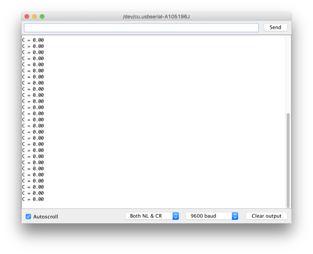
One of the reasons I found was that CS pin should be LOW state while reading a data from MAX6675 via MISO, but CS remained HIGH state.
I checked my circuit schematic and wiring over and over, but I couldn't find the reason why.
breadboard test
To test my board more flexible, I reconfigured my design onto a breadboard. I used SOP-DIP breakout board for ATtiny45 and MAX6675.
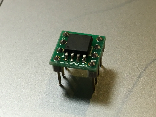
Sadly, the test result was the same, CS stayed HIGH and the zero reading.
I removed a MAX6675 chip and uploaded a simple sketch to monitor whether CS state could change its state. I could check ATtiny was working properly.
I decided to ditch MAX6675 and use a MAX31855 breakout board (adafruit) instead.
problem#3: ATtiny45 doesn't support SPI.h
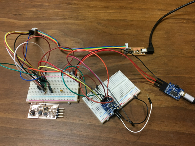
I tested ATtiny45 with MAX31855 breakout board on a breadboard.
I used a MAX31855 library and modified an example sketch. I tried to compile it but I couldn't. MAX31855 library includes SPI library, but the problem was that ATtiny didn't support it.
problem#4: memory map difference
I went back to a MAX6675 library. I thought I might be able to use MAX 6675 library with MAX31855 chip because they seemed to be same difference to me.
The result was a sort of successful but not perfect. Thermocouple sensor sent back a sort of reading data, but it's not stable at all. Reading data changed between a sort of proper value and nan(no data) intermittently.
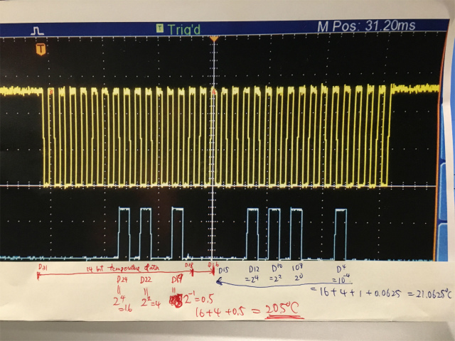
I delved into their datasheets (MAX6675, MAX31855) and what I found (with significant support from Yamamoto-san, again) were that MAX31855 and MAX6675 had different memory maps. MAX31855 and MAX6675 send back 32 bits and 16 bits data, respectively. MAX31855 has 14-bit temperature data and, MAX6675 has 12-bit.
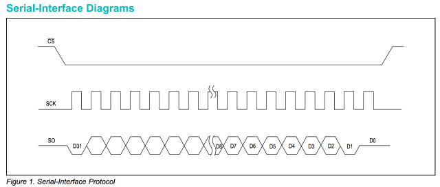


In MAX6675's library, a function dealt with 16-bit data, so I modified to be able to deal with 32-bit data for MAX31855. In addition to that, I used bit shift "V >>= 2" to ignore D17/D16 and read 14-bit temperature data (from D31 to D18).
Originally in case MAX6675 "v >>= 3" ignores from D2 to D0 to read 12-bit temperature reading( D14 to D3 ).
double MAX6675::readCelsius(void) {

  uint16_t v;
  uint16_t v1;       //added

  digitalWrite(cs, LOW);
  _delay_ms(1);

  v = spiread();
  v <<= 8;
  v |= spiread();
  v1 = spiread();    //added
  v1 <<=8;           //to read
  v1 |= spiread();   //lower 16bits

  digitalWrite(cs, HIGH);

  if (v & 0x1) {       //modified from "if (v & 0x4)"
    // uh oh, no thermocouple attached!
    return NAN;
    //return -100;
  }

  v >>= 2;    //modified from "v >>= 3;"

  return v*0.25;
}
Now I've got proper readings!!!
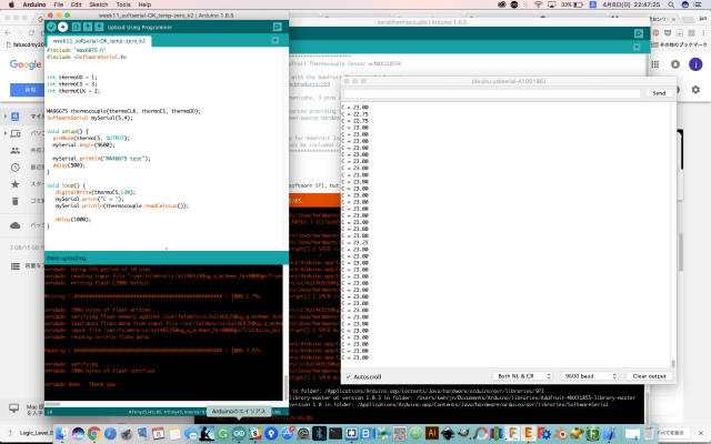
my ATtiny board and commercial MAX31855 breakout board
I redesigned circuit schematic to put a pull-up resistor, milled a PCB and soldered all componemts. I connected it with MAX31855 breakout board via SPI interface.
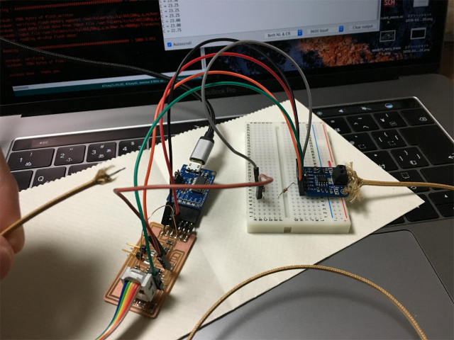
And here is the hero shot.
I could read the temperature from oscilloscope! Yellow wave was SCK, and blue wave was MISO.
files
ATtiny45 with MAX6675 board (Eagle schematic/PCB layout; toolpaths for traces/interior): archived format (.zip)
modified attiny board : archive format (.zip)
modified MAX6675 libraries: archived format (.zip)
Arduino sketch: Arduino IDE format (.ino)