Week 3. computer-aided design
Assignment
- model (raster, vector, 2D, 3D, render, animate, simulate, ...) a possible final project, and post it on your class page
As a homework assignment this week, I modeled what I needed for the final project. They are surfboards, waterproof containers, fins (optional). I am planning to mill the surfboard to the 8th week (make something big) and intend to print the containers 3D in the 5th week. Also, I designed 2D for the final project's original logo.
surfboard design with 3D software
software
I chose a CAD software specialized for surfboard design. I used AKU Shaper from that software based on this great documentation. There are other softwears and interfaces were pretty much the same.
| AKU Shaper | Free Two Week Trial | monthly subscription($45 / month) available |
| Shape3D | Free(lite) | costs 435 € a year to export STL files |
| BoardCAD | open source | trouble with exporting STL files |
modelling
I do not have any knowledge about surfboard design, and I do not want my original design to ruin the final project, so I decided to copy my existing surfboard design
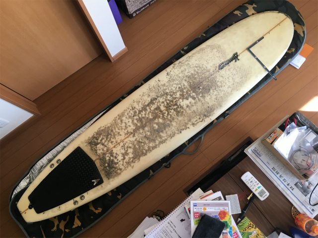
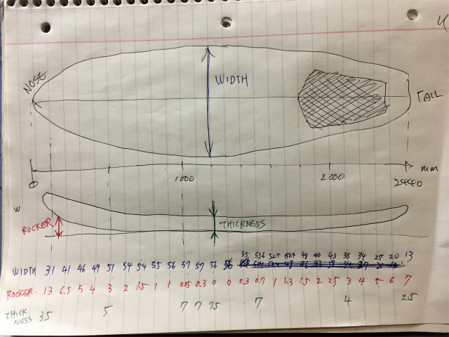
First, I measured my board dimensions. The length of the board was 2440 mm(96 inches), the maximum thickness of was 750 mm(29.5 inches), and the maximum width was 560 mm(22 inches).
I started the application and opened and chose the blank board, which is appropriate for the size I'm going to design.
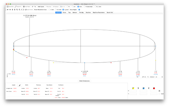
I can modify the surfboard profile freely by moving blue bezier points.
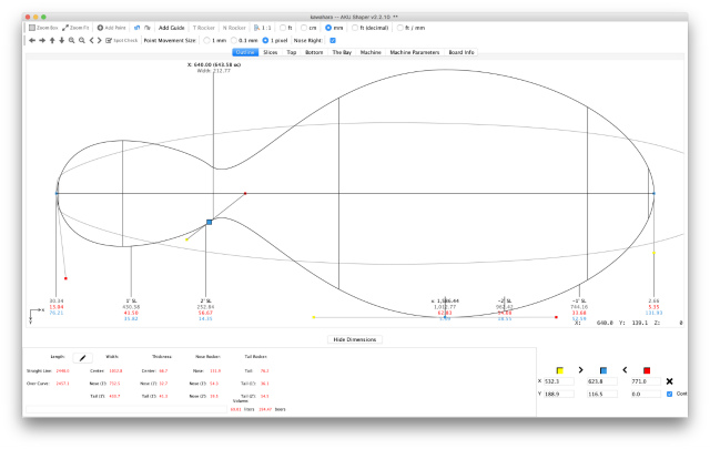
I added blue bezier points on the board profile at every 100 mm from the nose of the board.
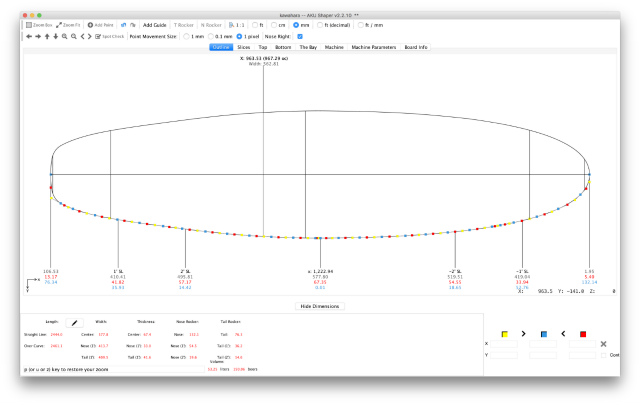
I adjusted blue bezier points to match my surfboard.
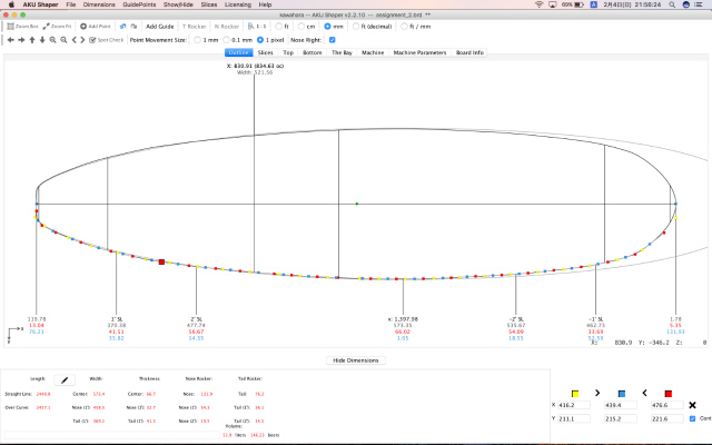
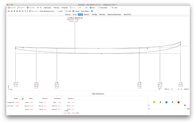
Then, I adjusted the rocker profile, too.
I exported my design in STL format and opened in 3D printing slicer software(Simplify 3D). It looked like my surfboard.
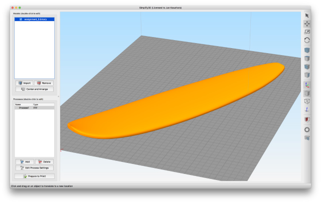
The model file
AKU Shaper format is here
STL format is here
After modelling
I didn't realize there are CAD tools specialized in designing a surfboard. There was a tutorial to design a surfboard with Fusion 360, but It doesn't look easy enough. Now that I understand the reason there are specific industry-oriented CAD softwares.
I wondered if there were any CAD for a particular purpose? I did some my homework.
| Fasion(pattern making) | Optitex‘s ODev, OPro and OSel programs; Kaledo from Lectra; Telestia Creator; FashionCAD and etc. |
| Footware | Romans CAD; Shoemaster CAD; ICad3D+; ElitronCAD 2D Footwear; great list is here |
| Architecture | AutoCAD Architecture; Chief Architect; TurboCAD; BricsCAD; ProgeCAD and etc. |
watertight enclosure design
As a design of a watertight enclosure, I assume a box like an image shown below. There is a groove in the top of the box wall, and rubber-made O-ring is placed in it. There is a convex part on the back side of the lid. When the lid is placed on the box and pressure is applied, the O-ring will be crushed, and the waterproof will be achieved
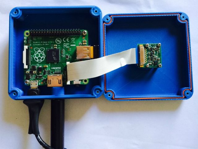
software
I used AutoDesk Fusion 360 for my box modelling.
modelling
First, I drew a rectangle sketch on XY plane and extruded the profile plane.
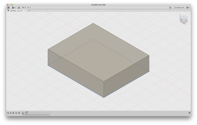
Then "Modify/Shell" the box and place a lid as a "New Body" on the top of the box.
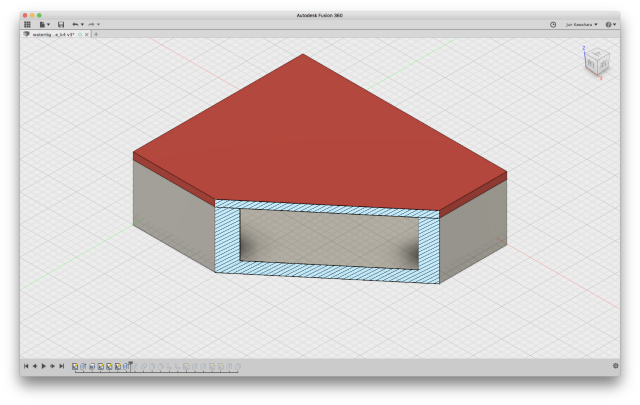
Select the top of the box as the profile plane and "Create/Sketch" a groove profile on it.
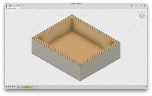
"Extrude" it from the back side of the lid with the operation "Join." then Modify/Combine" with the box as "Target Body" the lid as "Tool Body" and "Keep Tools"
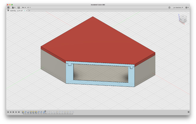
The operation made a groove on the top of the box.
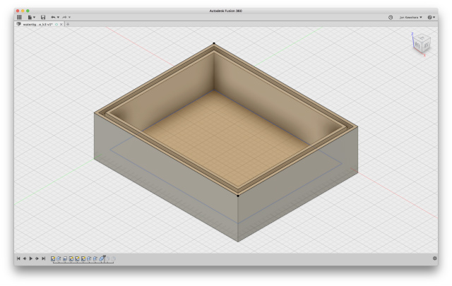
"Modify/Fillets" at all corners.
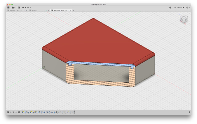
In this design, the wall thickness of the box became thick enough to be dug a groove, it takes time and material cost in 3D printing. Since sufficient thickness is needed in the part where the groove is formed, I redesigned as follows.
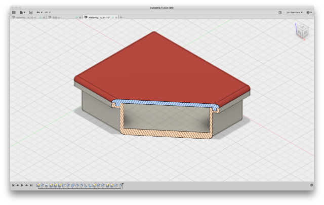
The model file
watertight enclosure 3d modelling: Fusion 360 format (.f3d)
After modelling
Since the concave-convex parts are the same size at this time, the 3D printed concave-convex part will not be inserted successfully. Considering such as to offset convex portions will be necessary. Also, I do not know how much the wall thickness (strength) necessary for waterproofing is. I am going to observe the product to make use of design for modeling.
One of my friends told me that there was no big O-ring if I design a box big. It is necessary to decide the size of the box required for storing the electronics and selecting an O-ring size close to the size of the box. Then you will need to redesign 3D modeling to fit that O-ring size. My friend also said that if the size gets bigger, I will have to use a rubber sheet. In that case, the groove may not be necessary. Furthermore, the double-sided tape would play the role of waterproofing. I will 3D-print a box and will test the waterproofness of them in the near future.
I know little about how to use Fusion 360 yet. I will practice, Practice and PRACTICE! Practice makes perfect. I am going to try softwares other than fusion 360.
surFABoard logo design
illustrator (vector software)
I know how to vectorize black and white raster images by Inkscape, but I did not know how to make a part of the photo image a vector image. So, based on this tutorial, I tried to create the surFABoard logo with illustrator. The operation is going to use "Compound Paths(Clipping Mask)."
Open an Image,
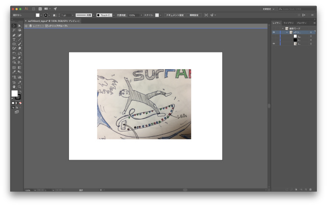
Making compound paths(using as a mask))
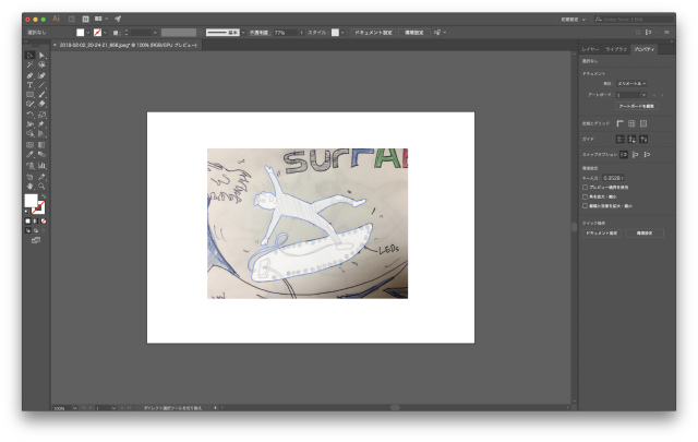
then, setting a mask made unwanted parts gone.
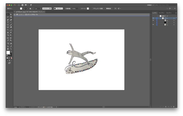
put a fabfont on it and done
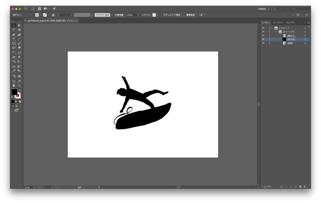
surFABoard logo
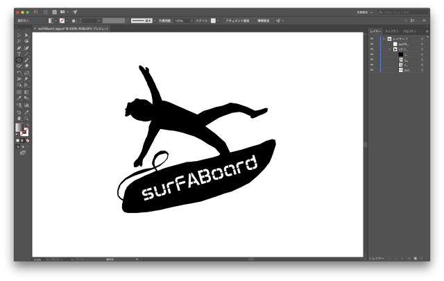
logo file (illustrator): download
After modelling, I have not understood the concept of "layer" yet. I am going to need more practice illustrator as well as Fusion 360.
gimp (raster software)
I also tried logo design with raster type software, Gimp.
First, open an Image and select sections, which I wanted to delete, with intelligent scissors tool.
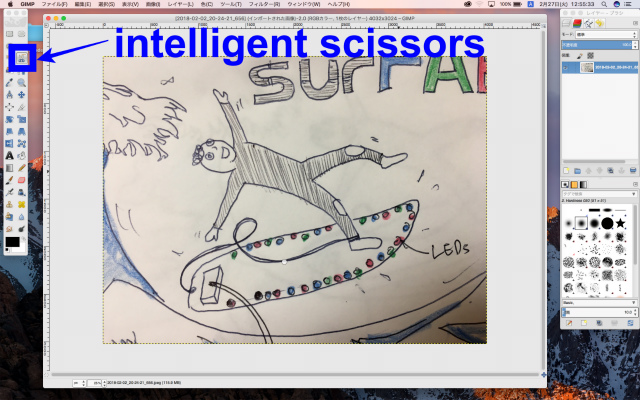
Then, delete them.
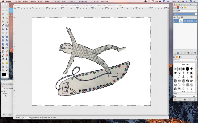
Paint black and put "surFABoard" text and rotate a bit.
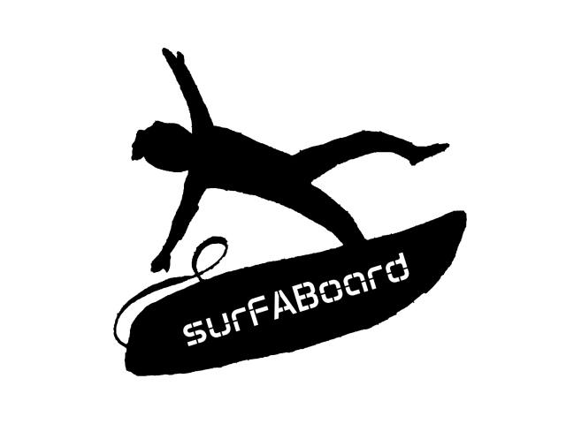
logo file (Gimp): download
The boundary line is not as smooth as a vector logo. I felt the vector software was suitable for a logo design.
files
surfboard 3D modelling: AKU Shaper format
surfboard 3D modelling: STL format
watertight enclosure 3D modelling: fusion 360 format (.f3d)
surFABoard 2D vector design: illustrator format(.ai), also scalable vector graphics format (.svg)
surFABoard 2D raster design: gimp format(.xcf), also portable network graphics format (.png)