
Input Devices

This week's tasks are:
- add a sensor to a microcontroller board that you have designed and read it.
- Describe design and fabrication process
For this assignment I decided to use a mic and capture the output signals from it.This also will be part of my graduation project.
* All datasheets, files and online refrences are attached at the end of the page.
Step1: Getting introduced to the sensor
- What is the electret condenser and how does it work
- Vcc: The operating voltage of the electret. Determined by the manfactureur to be 5V.
- R1: This resistor is used to bias the internal JFET of the electret. It's value is determined by the manfacturer to be 2.2 K ohm.
- C3: This capacitor is used to block the DC voltage and pass only the AC sound waves. DC Voltage Vcc is only for biasing power to the microphone. It should not appear on the output sound signal.
- Avd: Is the gain in voltage. this circuit is designed for gain 20, so if the output from the electret mic is 0.1 V this means that the output from the amplifier is 2V.
- We don't have 4.7uF in the inventory so I used 5 cpacitors of 1uf to give 5uf.
- We don't have 5 pF in the inventory so I used 5 capacitors of 1pF to give the 5pF.
- I'm not using speakers so I will connect pin 5 and 8 from the amplifier to two pins from attiny44 to read the output.
- I draw the circuit schematic and board using Eagle software.Detailed instructions on how to use Eagle to draw schematic, board and generate requied files for milling visit Electronics production and Electronics design documentation.
- Fab Library
- SMD voltage regulator library
- pin header2 library
- 2 pin header: PINHD-1X02_2.54-SMD-90°
- slide switch: SPDTSWITCH
- ZLDO1117 voltage regulator: V_REG_LM1117SOT223
- Capacitor: CAP-US1206FAB
- Resistor: RES-US1206FAB
- Electret mic: ELECTRET_MICROPHON-WM-61B
- Variable resistance: TRIM_EU-CA9V
- LM4861 amplifier: LM4871LM4871MX/NOPB
- Attiny44: ATTINY44-SSU
- Resonator: RESONATOR
- FTDI headers: FTDI-SMD-HEADER
- ISP pin headers: AVRISPSMD
- The Power circuit: It consists of a slide SPDT switch to switch the power on and of and hence turn the whole circuit on or off. and a voltage regulator to maintain the input power to 5V.
- The Audio circuit: That consists of the mic and ampilifier circuits described on steps 2 and 3.
- The Attiny44 circuit: That has the attiny microcontroller to be programmed with the desired code and the FTDI for serial communication and monitoring. This circuit is described more at Hello echo board in Electronics design week.
- switched to board mode and made the layout of the PCB
- The test was done at a fixed distance between the mic and the mobile phone (20 CM)
- Reading the Values from Attiny44 using ADC and serial monitor
- What is diffrential Amplifier
- What is diffrential ADC
- Check the signal in serial monitor
- Check the signal in Arduino Serial plotter
- Attiny 44 datasheet.
- LM4861 amplifier datasheet.
- ZLDO1117 regulator datasheet.
- Detailed paper about electret mic and amplifiers.
- Fab Library
- Pinheader-2 library
- Audio circuit Eagle file.
- Audio circuit traces milling file.
- Audio circuit outline cutting file.
- Arduino code for reading amplifier outputs.
- diffrential amplifiers paper from texas instruments.
- C code of plotting audio signal using arduino.
- How to build an electret microphone circuit.
- The electic electric microphone.
- using image to lithophane website tutorial.
- Arduino VU meter.
- How electret condenser microphone works.
- Spark fun tutorial about ADC.
- how to use attiny adc in diffrential mode.


Electret mic inner construction
Electret mic actual photo

The electret consists of two main things Capacitor and JFET
It has two electrodes with a gap between them that acts like a parralel plate capacitor with a fixed charge bonded to its surface. Air pressure variations (sound waves) move one of the electrodes of the capacitor back and forth, changing the distance between the two electrodes, and change the capacitance of the structure. Because the charge on the microphone is fixed, varying the capacitance causes the voltage on the capacitor to also change, satisfying the equation:
$$Q = {c} \times {V}$$Where Q is charge, C is capacitance, and V is voltage.
JFET is a transitor whoes current flowing between drain and source changes by changing the biasing voltage ( the voltage on its base).
The voltage signal produced by sound modulates the gate voltage of the JFET, labeled VG in the above image causing a change in the current flowing between the drain and source of the JFET (IMIC).An extremely high resistance RG is included to bias the gate of the JFET.
Step2: The electret basic circuit
I have searched for my electret mic manfacturer to check the datasheet and the connection recommended. I got my mic from EPE ELECTRONIC CO.
I found that this is the simplest circuit to make the electret mic working.
R1 and C3 together form a high pass filter. It's a filter that passes only frequienceis higher than a certain Cutoff frequency and attenuates frequencies lower than the cutoff frequencey.The value of this capacitor should be calculated at a very low cutoff frequency to not attenuate any signals.
$$C_3 = {{1}\over {2\pi R_1f_c}} = {{1}\over{2\pi\times2200\times5}}=1.4\times10^-5=14\times10^-6=14 uF$$I used 10 uF capacitor

Step3: The amplifier circuit
The output signal from the electret mic is very small and the variations in the signal are not really measurable on very small values so I needed to amplify the output signal from the electret mice to amplify the variations and make it scalable to use these variations in my code. As described in the previous step the output signal is in voltage and we need to boost this voltage to be able to read it.
I have already tested the circuit the LM386 audio amplifier but my instructor insisted on using the amplifier we have in the inventory LM4861.It was a little bit challenging as it has a lot of features that I don't really need in my project but I started to explore it.
The LM4861 is a bridge-connected audio power capable of delivering 1.1W of continuousaverage power to an 8Ω load using a 5V power supply.
The output voltage is taken from output pin Vo1 with reference to output pin Vo2 not like most of the amplifiers who give the output signal from one pin with refrence to the ground.


This circuit is from the datasheet of the amplifier
Step4: Designing the circuit
The libraries required for this design:
*all libraries are attached at the end of the page.
The components I used with their names in Eagle:
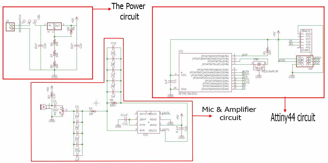
The circuit consists of 3 main parts:

The voltage requlator circuit from the datasheet.
The voltage requlator we have in the inventory is ZLDO1117. It's a voltage regulator with adjustable output.The output value depends on the resistors connected to it.
To have consistent 5V output the resistor should have a ratio of 3:1 as shown in the picture.
I used three resistors of 100 ohm in series then only one 100 ohm as shown in the schematic to give 3:1 ratio.


After finishing the board I decided to try the plygon.For how to write the text check Output devices week documentation.
Select the polygon tool then draw a line over the dimension lines.


Click on the ratsnet tool to make the polygon.
From the info tool double click on the polygon and change the width to 16 mil and isolate to 24 to not make any errors during the milling.

The last step is to connect the polygon to the ground by giving it a GND name using the name tool.
After making the DRC( Design Rules Check) generate the milling and cutting files as described in Electronics design week.


The final board with total dimensions of 7x7 Cm.
The traces file for milling.
The outline file for cutting.
Step5: milling, soldering and testing


Prepare milling and cutting files using fab modules and do the milling on roland MDX-20 milling machine
For more detailed instructions on how to use fab modules for PCB milling check Electronics production week documentation.

The milling result.
Before starting the soldering I always check the PCB with Avometer and the buzzer tool for short circuits or unconnected wires.


Wrong Regulator package
After finishing all the errors prepare the tools and start soldering.
I That I used wrong package for the regulator 23 instead of 223 so I edited it in the design then remilled it again.After finishing I started soldering.


In sodering I added two wires one to measure the mic output using the oscilliscope and the other to measure the amplifier output.
Solder a zero ohm resistance between amplifier pin 7 and the ground.
After soldering I discovered that pin 7 of the amplifier was not connected to anything and in the datasheet it was stated that it shouldn't be left floating and should be connected to the ground so I soldered it to a GND trace using 0 ohm resistance.I also soldered the switch pins as it will take its power from the ISP and FTDI power pins through the programming and testing and no need for an external power source.
Step6:read the output
I decided to read the output from the mic directly then from the amplifier output and from the attiny reading through the serial port and compare between the results.
Frequency will be changed using an app I downloaded on my mobile ( there are hunderds of applications on app store) to generate frquencies.


Connect the oscilliscope probs between the mic output.
When there is no set frequence the output signal from the mic is almost zero.
I used a portable oscilliscope that belongs to my husband but all oscilliscopes work in the same way. each channel has a prob that has two terminals, these two terminals should be connected between the two points of the output we want to measure.make sure that the probs is not damaged, I wasted a lot of time thinking that my board is not working as I was not recieving any reasonable signals on the oscilliscope while the whole problem was just in the Probs.


The mic output signal is in milli volt.
The amplifier output signal is in Volt.
The readings I got:
| Frequency (HZ) | Mic output (mv) | Amplifier output (V) |
|---|---|---|
500 |
27 |
0.43 |
600 |
32 |
0.48 |
700 |
39 |
0.61 |
800 |
40 |
0.71 |
900 |
44 |
1 |
1000 |
52 |
1.12 |
Calculate the actual gain from the readings:
$$Gain = {V_{out}\over V{in}}={\sum V_{out}\over \sum V_{in}} = {{(0.43+0.48+0.61+0.71+1+1.12)*1000} \over{27+32+39+40+44+52}}=18.8$$Perfect! I got a gain on 18.8 which is really close to the 20 gained I designed the circuit for.
I wrote an arduino code to read the output of the amplifier using the ADC pins in the attiny44 and send the readings through the FTDI cable.
For more info about how to program the board check the Electronics design documentation and Embedded programming documentation.


Connect Fab ISP for programming and FTDI for serial monitoring.
Upload the code and check the values through the terminal.

In the code the attiny pins should be used in their equivilant numbers in arduino boards.
#define RX   0   // connected to attiny44 pin 12
#define TX   1   // connected to attiny44 pin 13
#define VO1  3 // connected to atting44 pin 10
#define VO2  2 // connected to attiny44 pin11
int output2=0;
int output1=0;
int result=0;
SoftwareSerial mySerial(RX, TX);
void setup() {
  // put your setup code here, to run once:
pinMode(RX,INPUT);
pinMode(TX,OUTPUT);
pinMode (VO1,INPUT);
pinMode (VO2,INPUT);
mySerial.begin(9600);
}
In the code I included the software.serial library to configure my TX and Rx pins then I defined the pins where the Rx and Tx are connected also the VO1 and VO2 pins. I then defined some integers to be used in the code.
I then Configured the inputs and outputs and the serial baud rate.
void loop() {

output1 = analogRead(VO1);
output2= analogRead (VO2);
result=(output2-output1)*20;
mySerial.print(output1);
mySerial.print(",");
mySerial.print(output2);
mySerial.print(",");
mySerial.print(result);
mySerial.print(",");
mySerial.print(ADCL);
mySerial.print(",");
mySerial.print(ADCH);
mySerial.print(",");
mySerial.print(ADC);
mySerial.println();
delay(500);
}
I then read the output1, output2 sent them through the serial monitor. also added an equation to read the difference between then and then multiply with 2 to amplify the small differences. Also tried to read ADC,ADCH.ADCL( will be explained more in the next section).
I was able to read the data but I though that it's a little bit random and can't be taken as a refrence in coding so I went for a more complex approach which is using the diffrential ADC property in ATTINY boards!
Step7:Diffrential ADC
The single endded amplifier has a single output with refrence to the ground. The diffrential amplifier has two outputs ( called diffrential outputs) and the output signal is measured between these two outputs. In another meaning the output is measured from one output referring to the other output instead of the ground.


The amplifier that I'm using LM4861 has diffrential output.
ADC or analog to digital converter is used to convert the analog data comming from sensors to digital signals to enable microcontrollers that works with only digital read that data.
The Attiny microcontrollers pins have the feature of ADC and diffrential ADC. So if the input signal is single endded, ADC will be use. If the input signal is diffrential, diffrential ADC will be used.
I used the code that prof. Neil uploaded in Input devices week schecule under the sound section and modified it to work with my circuit(Attiny 44 and LM4861 amplifier) as it was written for Atting 45 and another amplifier. This code is written in C and it was really hard for me to understand it all so I started to figure out the parts that matters and leave the rest of the code as it is.

At the first part of the code I changes the serial communication configruation to PortA and the TX ( will be connected to FTDI Rx) at PA1 as connected in my circuit.

This part of the code is to configure the diffrential ADC settings in the attiny 44 and to understand it I had to go deep in the datasheet.

The Attiny do the ADC and diffrential ADC through a multiplixer and there is a "ADMUX – ADC Multiplexer Selection Register" which is used to change the channels or the voltage refrence.

The first two bits are for selecting the refrence voltage to be internal (1.1 V) or external ( VCC) and the rest of the bits are for selecting the pins that you are using on attiny and the gain that will be added to the result.


From the tables above I chose the internal voltage refrence and the PA3 and PA2 where I'm connecting my amplifier outpu1 and output2 and gain is one.
And I set BIN bit to 1 ro enable the ADC and ADLAR bit to 1 to lower the overall ADC resolution to 8 bit instead of 10 bit.

The changes I made on the ADC configuration part
When the ADC conversion is done, the results can be found on ADC registers (ADCH and ADCL). In the code it stores the data in two arrays one for ADCH and the other for ADCL. These data are Bytes and I wan't able to send Bytes through Arduino Serial monitor so I checked the data using termite software and decided to use latest version ofArduino to use the serial plotter option.
The Arduino Serial plotter use the data that is sent through serial monitor but instead of just display the data it plots these data.
Serial.print(temperature);
Serial.print("\t");
Serial.println(humidity);
put_char(&serial_port, serial_pin_out, array_lo[i]);//serial print ADCL
put_char(&serial_port, serial_pin_out,9); // print tab
put_char(&serial_port, serial_pin_out, array_hi[i]);//serial print ADCH
put_char(&serial_port, serial_pin_out, 10); // print new line
This is How the commands should be written if we need to plot multiple variable in serial plotter.print the value of 1st variable then tab then the data of the second variable in new line
This is what I made in the code. Print ADCL, print tab, print ADCH and print new line.
The baud rate was 9600 and I speeded it up upone a recommendation from our local instructor Haggag to 19200 by changing the bit_delay_time to 51 instead of 102.
For more detailed instructions on how to upload a code using Arduino IDE and Fab ISP programmed check Electronics deign week documentatio.

In termite open settings, Set the baud rate to 19200 and the reading to HEX. Also make sure that the right com is selected.
The output reading in termite.


