Computer-Aided Design
Task Requirments:
- Model experimental objects/part of a possible project in 2D and 3D software
- Show how you did it with words/images/screenshots
- Included your original design files
Choosing My Software
I have a fair knowledge with fusion 360 and i beleive it will do all the tasks required just fine, so i have decided to try a new software before i go with fusion.
I decided to try Shapr3d an Ipad Pro cad software, there is a free plan wioth limited features and paid plan that costs 150$ /year, i went with the free plan and 3d modelled my final project proposal.
Shapr3d
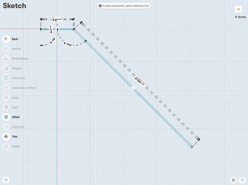
First I sketched my design with a left side prespective.
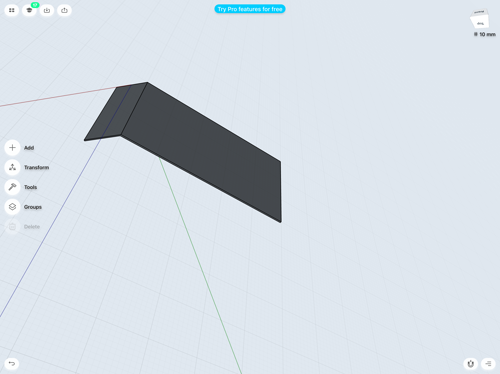
Then I extruded the whole body to my desired width.
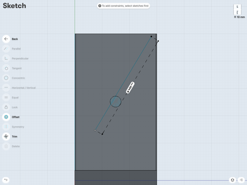
I sketched a circle with the diameter of my axis on the face of the body and extruded it in a symmetrical 2 directions performing a cut in the body, then i sketched a rectangle on the top of the axis with the slider dimensions and extruded it through the axis performing a cut.
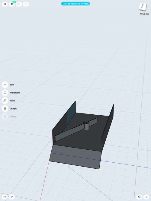
Review:This app is very handy and easy to use software, it's missing lots of features "specially in the free version", so in my opinion it's a good tool to just sketch in 3d on the go specially for people with bad free sketching skills like me and it's also a very good tool to model simple objects for 3d printing on the go as it exports for 3d printing.
Fusion 360
I have already made a 3d model of my final project proposal on the first week assignment first week assignment so i decided to go further with this assignment and start to model my project as assembled components to be ready for cutting and i used parametric designing to facilitate any modifications in the design over the course of the academy.
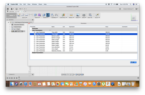
Parametric Design:
Definition:
Parametric design is a process based on algorithmic thinking that enables the expression of parameters and rules that, together, define, encode and clarify the relationship between design intent and design response.
Simply define all the dimensions of the your model and enter it's values in the parameters tab in fusion, and when sketching just enter the name of the parameter instead of the value.
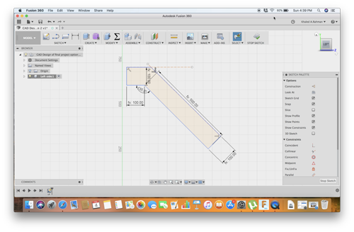
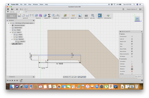
Sketching Left Side
I started sketching the sides of my attachment "with parametric dimensions" as i desided that these side will be holding the whole structure.
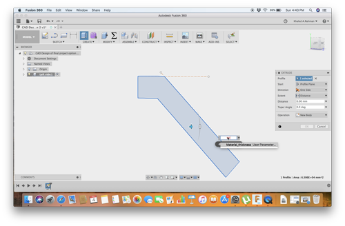
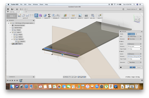
Extrusion of Left side
I extruded the left side to a value equal material thickness.
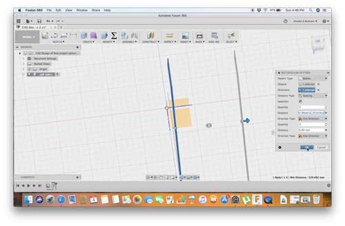
Cloning Right Side
I clonned the right side throug the rectangular pattern in modify from the left side body with a value equals to bottom width + material thickness.
Sketching Top Part
I sketched my top part on the left side.
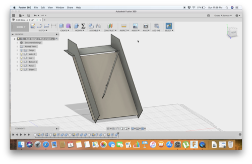
Extruding Top Part
I Extruded the top part with a 2 way extrusion one with the value of "fixing teeth" and the other of value of "top width + material thickness + fixing teeth".
2D Software design:
I decided to design a simple box to keep my screws and nuts
I choose Inkscape to do this job.
First i watched This tutorial to make press fit box on inkscape.
I setup the page size to 500X300mm "size of plywood sheet" and the grid to 1mm
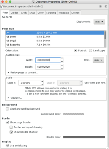
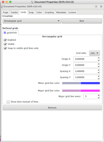
I decided to make the box dimensions (200X100X100).
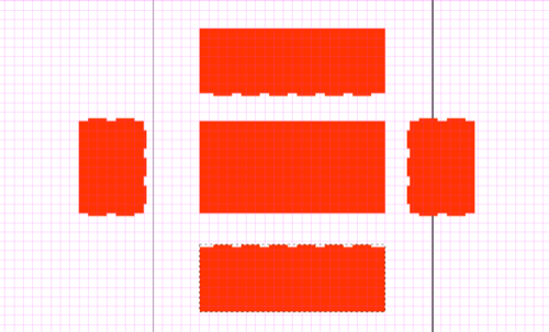
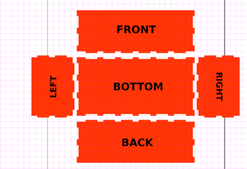
So i started with drawing the bottom while setting the dimensions from the menu bar on the upper left corner.
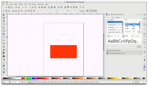
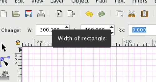
Following the same technique i draw the front,back and 2 sides.
Then i draw a small box 6X10 mm to act as the slots and i cloned it to my prefered places.
First i used copy instead of cloning but it didn't work for the union and difference commands, after inspecting i figured out that the copy paste, pastes image instead of vector.
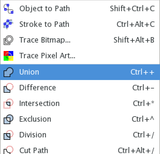
I used the unioncommand to join the tabs to the parts.
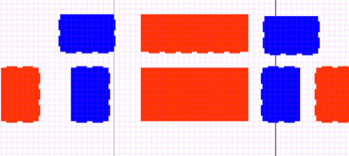
I made copies of the parts with slots to use them to cut the slots "i changed there fill to blue to be noticed"
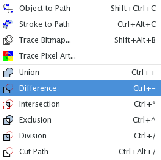
I used the Difference command to cut the tabs through the parts.
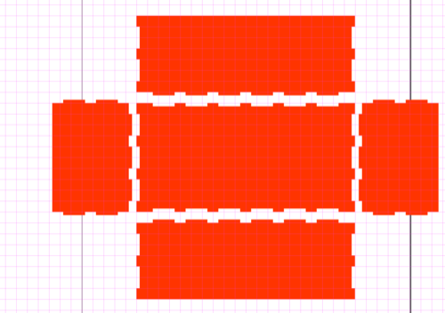
I added text for illustration purposes.
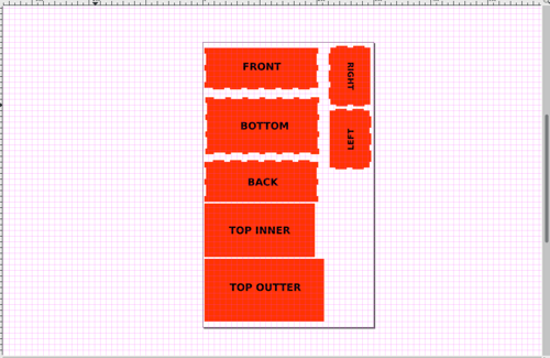
Finally i designed the cover as 2 peices to be glued together and fit inside the box.
I arranged the peices on the page to prepare them for laser cutting
I saved the drawing as SVG for future edits