Week 9
Molding and Casting

assignment
Group Assignment
1- review the safety data sheets for each of your molding and casting materials, then make and compare test casts with each of them
Individual Assignment
1- design a 3D mold around the stock and tooling that you'll be using, machine it and use it to cast parts


3D model .OBJ Download
Hexagon .STL Download
Hexagon .NC Download
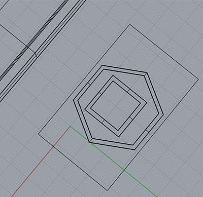
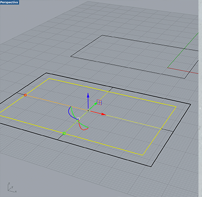
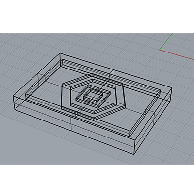
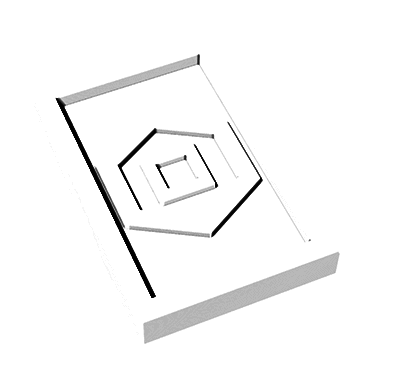
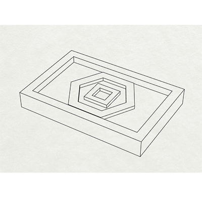
I decided to use rhinoceros because I wanted to make a .stl file with consistent vector information. In the 3D workspace I created a box around the ground plane and created an offset of 5mm. I created a surface on the larger box and extruded it down to 10mm (the material depth we are using).
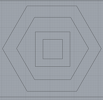
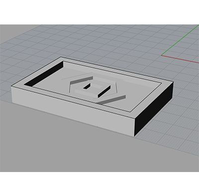
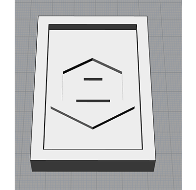
I made a surface on the interior box and extruded it down 6mm. Then I moved the geometry down 3mm and extruded it down another 3mm, creating a solid of it (this would be my positive after the mold). I exported this file as a .STL so that I could prepare a file to cut using Art Cam.
ArtCam
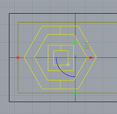
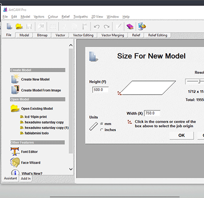
In Art Cam, I created a new file and set the dimensions to the same width and height in rhinoceros.
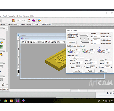
When you have the size and orientation correct you can center the file and place it.
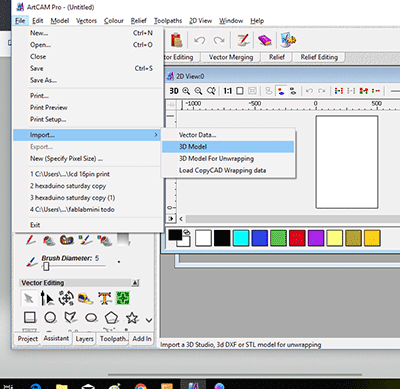
Once it is imported, you select the geometry and then you click the Machine Relief button and a list of menu settings appears.
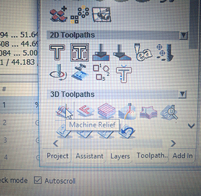
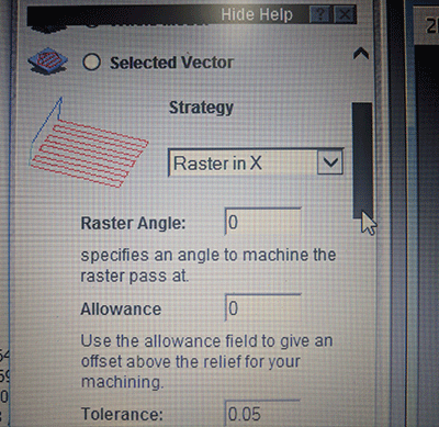
I wanted to do just one plane (x-plane) rastering.
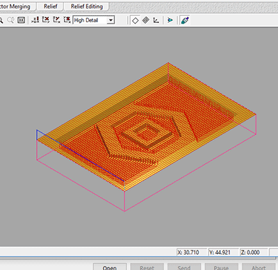
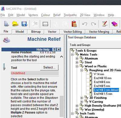
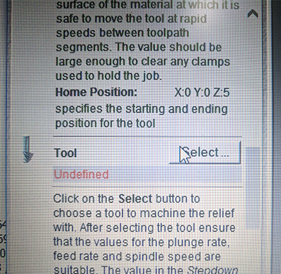
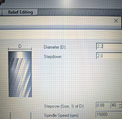
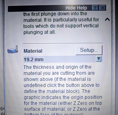
I selected the tool menu and set the build settings to use a 2.2mm plunge bit. I set the stepdown to 2mm over 4 passes to create the relief of my file.
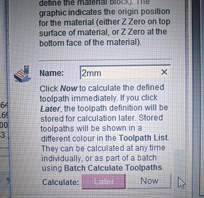
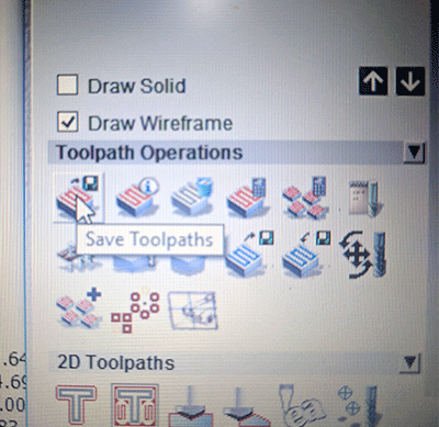
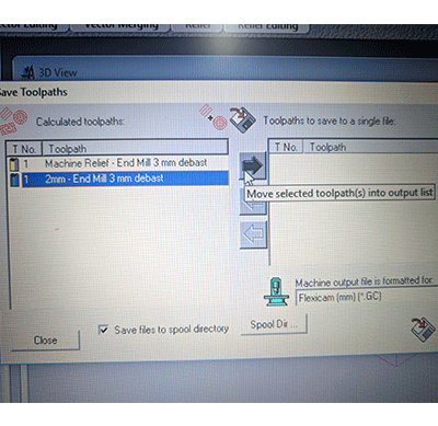
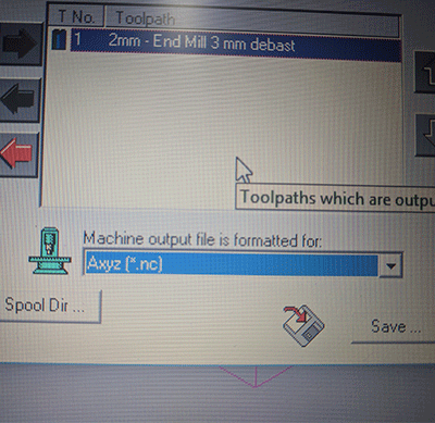
After the toolpath was created I renamed the file and clicked save toolpath to export the toolpath in gcode.
I saved the toolpath as a gcode .nc file to cut on our desktop milling machine.
Grbl Controller
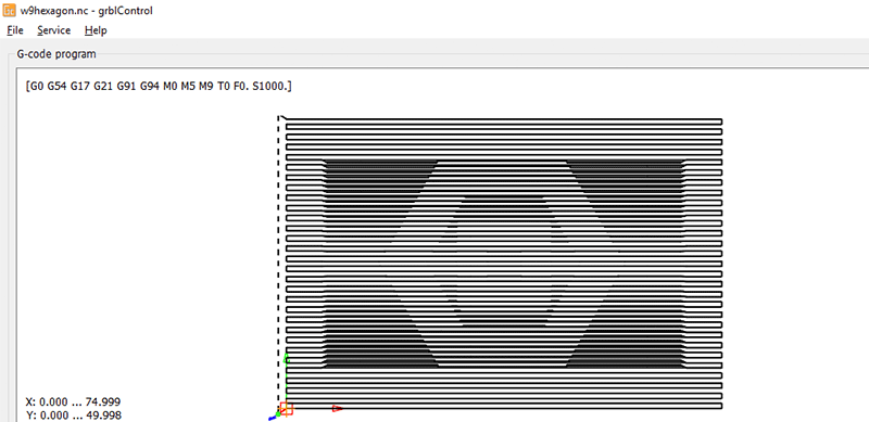
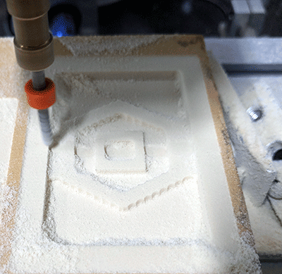
Next I opened Grbl controller and opened the .nc gcode file I had generated in ArtCam.
I secured the cutting material with double sided tape and positioned the mill on the physical plane.
I set my origins in the software and started the toolpath.
With my mold ready, I got out the 2 part materials to use for the assignment.
I reviewed the curing times and product information.
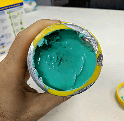
When I opened the container Part A had solidified into a solid mass.
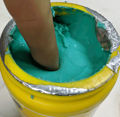
I went to the jewelry lab and was able to get a two part silicone rubber mold material.
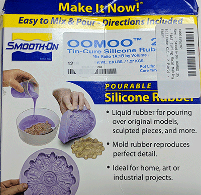
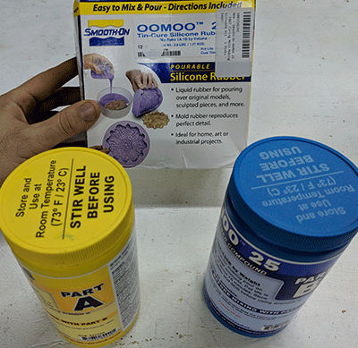
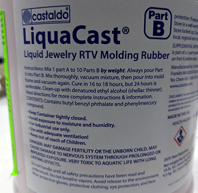
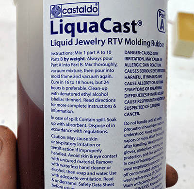
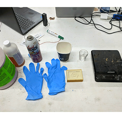
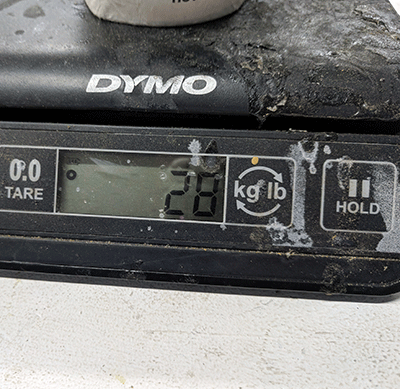
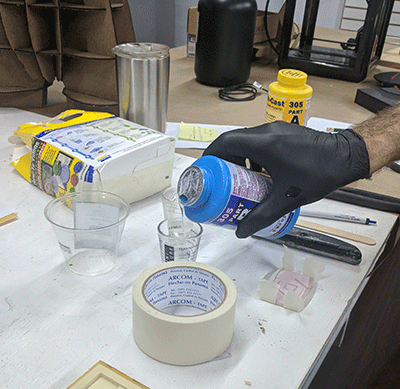
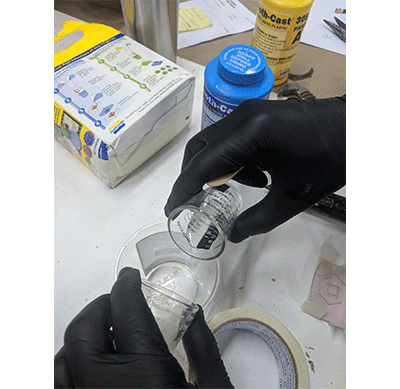
I put on latex gloves for mixing the two part components and measured out even amounts by weight on a scale in separate cups. The ratio for this is 10:1 part B:A. Next I poured part A into part B and stirred consistently for 2 minutes.
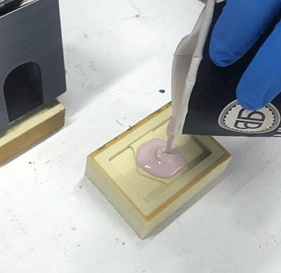
I sprayed the interior edges of the first mold with a silicon release agent.
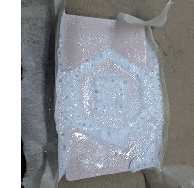
I poured the mixture into the mold and let it sit 12 hours overnight for it to set.
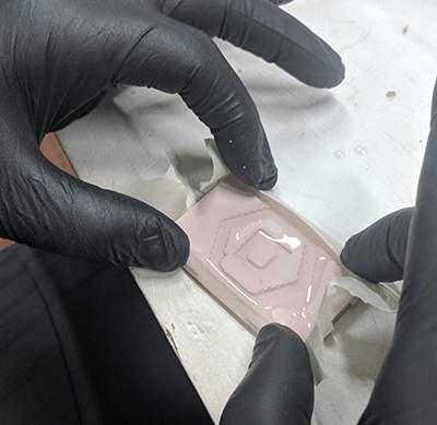
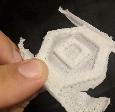
The next day, I went back to the shop and took the cured silicone out of the mold. The foam board did not give very much room and I didn't want to make any holes in the mold, so I got an exacto blade and tried to pry it from the edge. After finding a spot that moved from the edge I was able to get under it and pop it out.
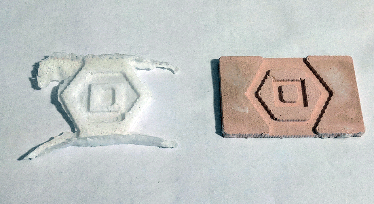
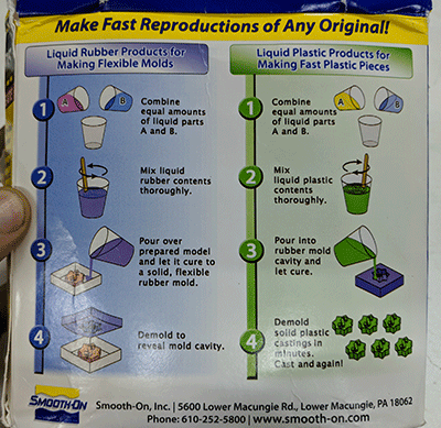
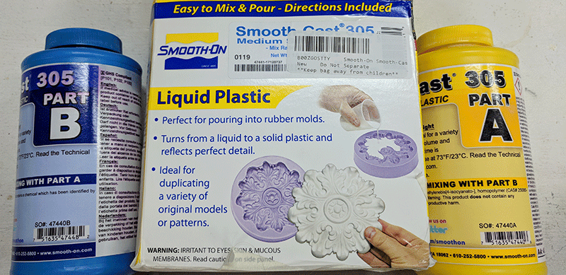
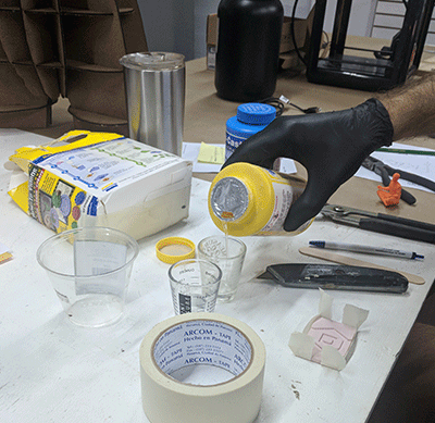
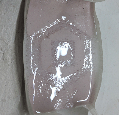
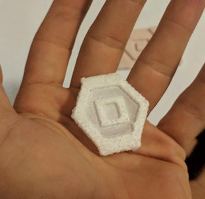
I prepared the liquid plastic and repeated the mixture of 50% / 50%, this time pouring into the silicone negative to create the cast file.
Another technique they use is vulcanizing. I have helped them cut steel tubing to create chambers to hold mold material, which they compress under heat and pressure. They use talcum powder to separate 2-part molds as well as pins to align them. Once the molds cool, they use them to spin-cast pewter in their centrifuges.
I wanted to design a part to include in my final project so I first tried to design a heatsink that could be molded in small sections. However, we managed to salvage some very efficient heatsinks and so I decided to create an gasket for the case of my final project instead. My goal was to be able to use the final piece of the assignment and use it to make a second mold in our foundry. That would let me create an aluminum foldable shape (like a strong, lightweight frame). I waited too long to use our silicon and the molding material coagulated so we had to order some more. Luckily, our jewelry department had some more and they let me use enough for the assignment. When I cut the test files I was able to get them desktop mill to work fine, however when I went to cut a mold on our CNC this time, it began giving me a familiar, troublesome problem. Midway through cuts it would plunge suddenly into the material. I tightened loose screws on 3D printed motor fixings and reduced the cut depth to 0.75mm in order for there to be less resistance on the bit and was able to cut out and make the molds for the assignment.
1- review the safety data sheets for each of your molding and casting materials, then make and compare test casts with each of them
Individual Assignment
1- design a 3D mold around the stock and tooling that you'll be using, machine it and use it to cast parts
Software Used
AutoCAD, Sketchup, Illustrator, Rhinoceros, Art Cam, Git,


Tutorial Used
Fab Academy Week 9 - Molding and CastingFiles used:
Vector lines .DXF Download3D model .OBJ Download
Hexagon .STL Download
Hexagon .NC Download
Walkthrough
I decided to use rhinoceros because I wanted to make a .stl file with consistent vector information. In the 3D workspace I created a box around the ground plane and created an offset of 5mm. I created a surface on the larger box and extruded it down to 10mm (the material depth we are using).
|
|
|
|
|
|
|
|
|
ArtCam
In Art Cam, I created a new file and set the dimensions to the same width and height in rhinoceros.
|
|
When you have the size and orientation correct you can center the file and place it.
|
|
Once it is imported, you select the geometry and then you click the Machine Relief button and a list of menu settings appears.

I wanted to do just one plane (x-plane) rastering.
|
|
I selected the tool menu and set the build settings to use a 2.2mm plunge bit. I set the stepdown to 2mm over 4 passes to create the relief of my file.
|
|
After the toolpath was created I renamed the file and clicked save toolpath to export the toolpath in gcode.
|
|
I saved the toolpath as a gcode .nc file to cut on our desktop milling machine.
|
|
Grbl Controller
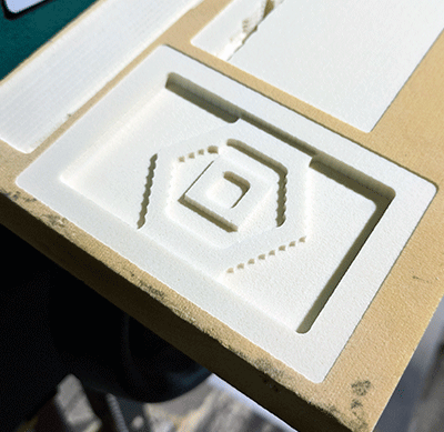
Next I opened Grbl controller and opened the .nc gcode file I had generated in ArtCam.

I secured the cutting material with double sided tape and positioned the mill on the physical plane.
I set my origins in the software and started the toolpath.

|
|
With my mold ready, I got out the 2 part materials to use for the assignment.
|
|
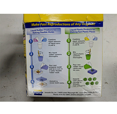
I reviewed the curing times and product information.
|
|
|
|
When I opened the container Part A had solidified into a solid mass.

I went to the jewelry lab and was able to get a two part silicone rubber mold material.
|
|
|
|
I put on latex gloves for mixing the two part components and measured out even amounts by weight on a scale in separate cups. The ratio for this is 10:1 part B:A. Next I poured part A into part B and stirred consistently for 2 minutes.
I sprayed the interior edges of the first mold with a silicon release agent.
I poured the mixture into the mold and let it sit 12 hours overnight for it to set.
|
The next day, I went back to the shop and took the cured silicone out of the mold. The foam board did not give very much room and I didn't want to make any holes in the mold, so I got an exacto blade and tried to pry it from the edge. After finding a spot that moved from the edge I was able to get under it and pop it out.
I prepared the liquid plastic and repeated the mixture of 50% / 50%, this time pouring into the silicone negative to create the cast file.
|
|
|
|
|
|

|
|
Conclusion
For the group assignment I asked our jewelry department to come up and talk to us about their experience with molding and casting. They design using software like Rhinoceros, Maya and CAD software like Matrix to make extremely precise sculptures and jewelry. They use FormLab 3D printers to cure resins, some of which can even be castable (meaning they can skip wax-injection molds and make heat-resistant ceramic molds). With that final mold, they can melt out the resin and pour metal directly into the mold.Another technique they use is vulcanizing. I have helped them cut steel tubing to create chambers to hold mold material, which they compress under heat and pressure. They use talcum powder to separate 2-part molds as well as pins to align them. Once the molds cool, they use them to spin-cast pewter in their centrifuges.
I wanted to design a part to include in my final project so I first tried to design a heatsink that could be molded in small sections. However, we managed to salvage some very efficient heatsinks and so I decided to create an gasket for the case of my final project instead. My goal was to be able to use the final piece of the assignment and use it to make a second mold in our foundry. That would let me create an aluminum foldable shape (like a strong, lightweight frame). I waited too long to use our silicon and the molding material coagulated so we had to order some more. Luckily, our jewelry department had some more and they let me use enough for the assignment. When I cut the test files I was able to get them desktop mill to work fine, however when I went to cut a mold on our CNC this time, it began giving me a familiar, troublesome problem. Midway through cuts it would plunge suddenly into the material. I tightened loose screws on 3D printed motor fixings and reduced the cut depth to 0.75mm in order for there to be less resistance on the bit and was able to cut out and make the molds for the assignment.