Week 02: Computer-Aided Design
Assignment
- Model (draw, render, animate, simulate, ...) a possible final project, and post it on your class page with original 2D and 3D files.
Learning outcomes:
- Evaluate and select 2D and 3D software
- Demonstrate and describe processes used in modelling with 2D and 3D software
Have you:
- Modelled experimental objects/part of a possible project in 2D and 3D software
- Shown how you did it with words/images/screenshots
- Included your original design files
My Process
Background
I already have a fair amount of experience with some of these tools. Inkscape I have used extensively for designing for the laser cutter (though the "clone" tool was new for me - I will need to play with that, as it has enormous potential). SketchUp I have used for many years for a variety of projects (though lately I have found it most useful for furniture layout / space planning). And TinkerCAD is something I teach to students in my Fab Lab and we use it to introduce the concepts of 3D modeling, CAD, and 3D printing.
My main goals this week are to:
- Become more familiar with AutoDesk Fusion 360
- Give FreeCAD a try as a 2D / 3D modelling tool
- Make some progress on CAD for my final project
I've chosen to go with Fusion 360 because I have a free Fab Lab license to use it on the machines at my Fab Lab, and I have already at least tried it before. FreeCAD is particularly interesting - I tried to use it in 2014 when I was at Open Source Ecology. I will be curious to see how it has developed since then, as I am always interested in using/supported the free and open-source movement.
Getting Started
I was most excited to work on CAD for my Rock-o-Matic cradle idea for a final project (and I think it will be important to pay attention to that excitement/interest level as I decide which idea to pursue as the weeks go by). Just to begin to wrap my head around the basic idea, I began with a hand-sketched schematic:
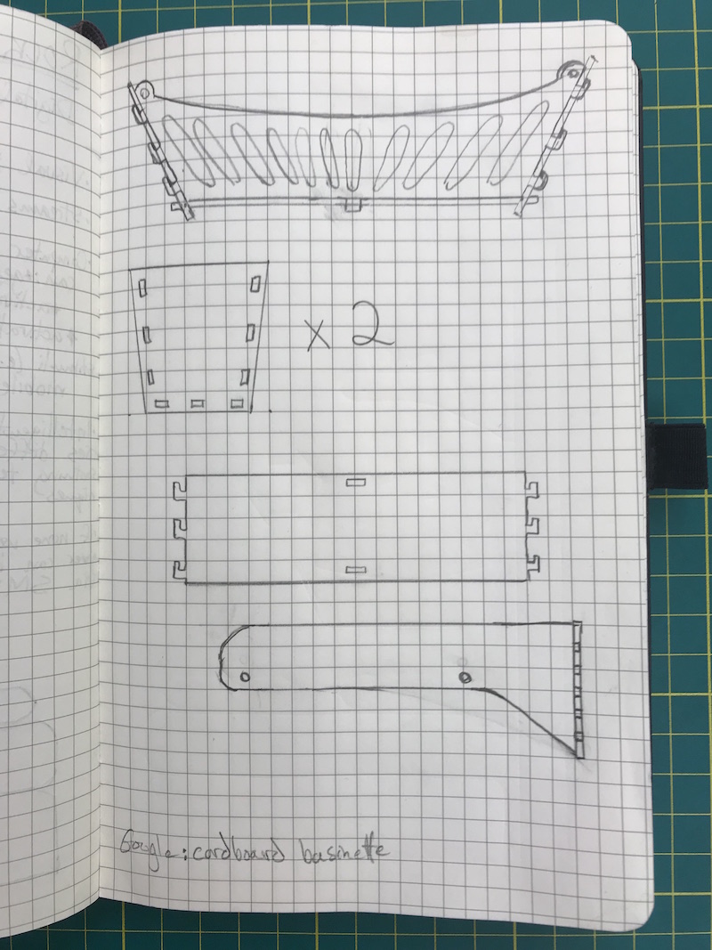
A quick google search turns up that a standard cradle/bassinet mattress dimension is 458mm x 916mm (18" x 36", but I'm going to try to do most measurements in this class in metric. I hope to CNC mill this cradle out of 11.9mm (15/32" or ~1/2") baltic birch plywood. This will set the dimensions of my base, as well as the tabs/inserts, etc.
CAD Steps
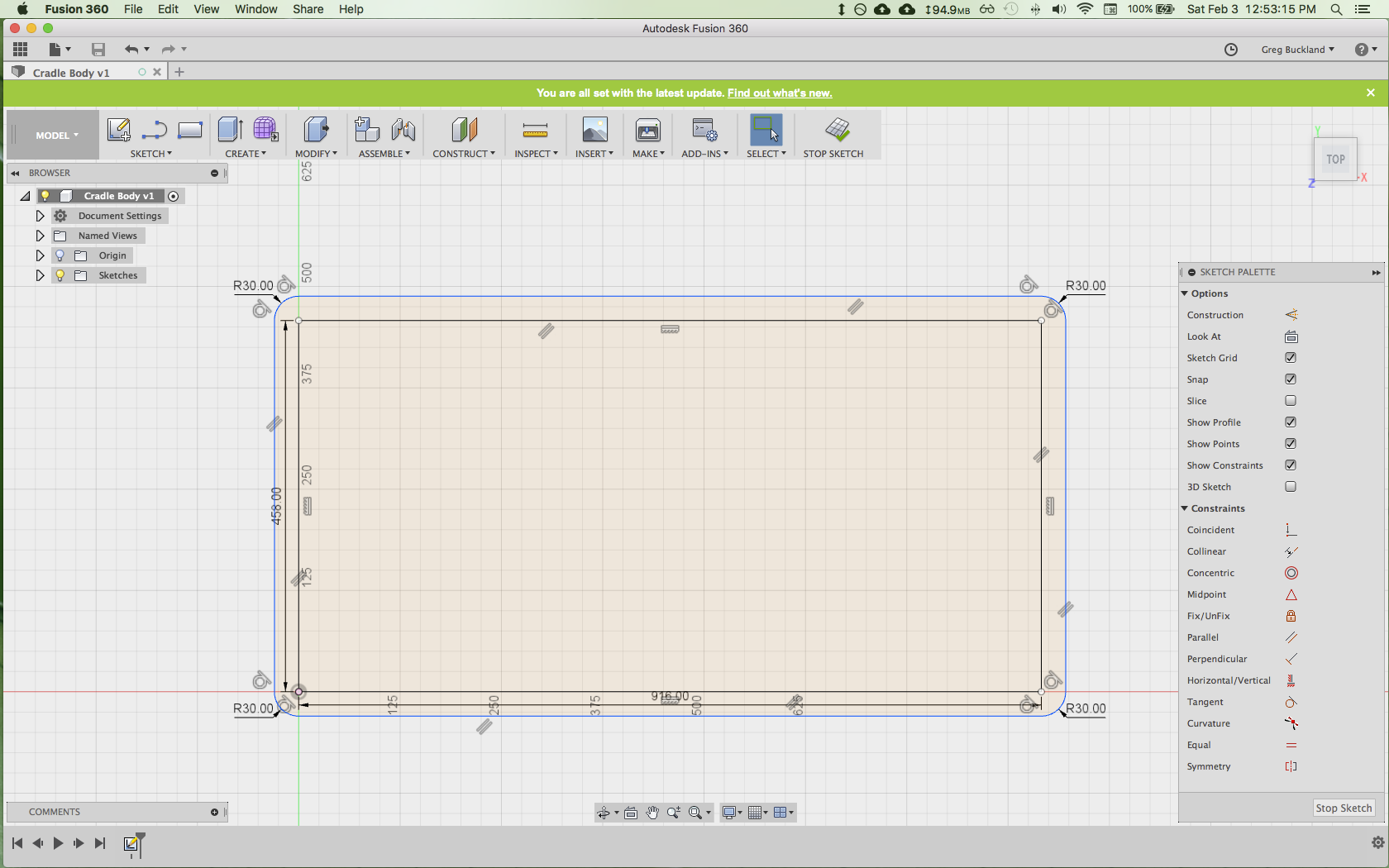
First, I created a 2D sketch of the base. I made a rectangle 458mm x 916mm to show where the mattress would go, and then used the sketch > offset tool to create a larger rectangle around it, offset by 30mm (to allow for the width of the Side and End pieces to come. I added fillets to round the corners.
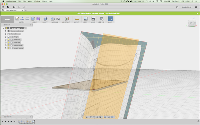
Next, I added the hand drawing to my CAD model as a canvass so I could trace it as a sketch
Side note: at a number of points I wasn't exactly sure how to proceed or what the best next step was. I realized quickly that there are many possible ways to do something in CAD, and rather than try to find the "right" or "perfect" way to do something, I should just try to find something that works. I'm sure in the future, after learning much more about Fusion 360, I might want to come back and do all these steps in an entirely different manner and/or redo this model in a different way. But I can only learn it by giving it a try!
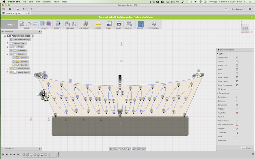
I made a 2D sketch of the cradle side, roughly following my hand drawing. I used the sketch > mirror tool to create a symmetrical sketch around a guide line.
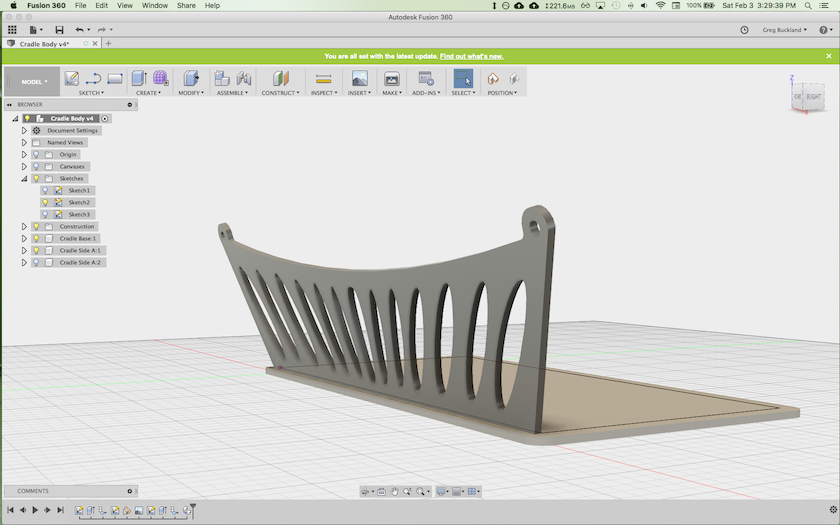
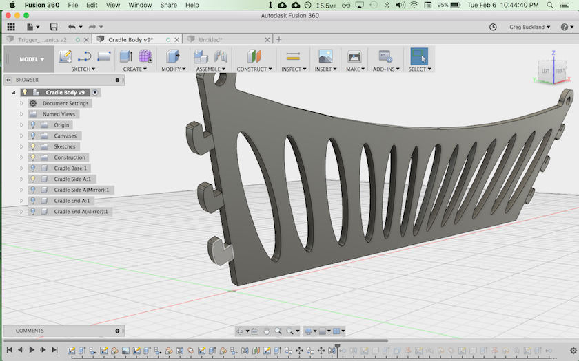
I extruded the 2D sketch into 3D to create a body. I then created a component out of the body and named it "Cradle Side".
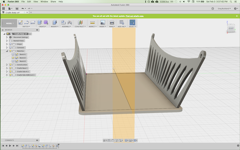
I drew a line bi-secting the cradle base, and created a plane perpendicular to the base along it. I used this plane to mirror the "Cradle Side" componenet across to the other side of the cradle base.
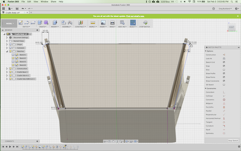
Next, I wanted to create the "Cradle Ends" - the pieces which would cap the cradle sides. I created a plane using the two farthest edges of the "Cradle Sides" and used this plane to sketch the shape of my Ends.
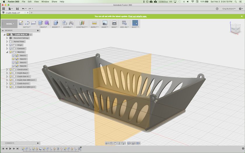
Repeating the procedure I used to mirror the sides, I created a perpendicular plane bisecting the cradle base, parrallel to the bottom edge of my cradle End. I used this plane to mirror the Cradle Ends. At this stage, the gross shape of my cradle was complete.
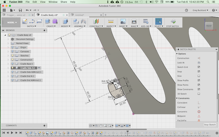
Next I began to model the finer details of my idea, specifically, the press-fit connection tabs between the sides and ends. These hook-shaped tabs will slide into receiver holes on the end pieces (as shown in my 2D hand drawing).
I extruded the tabs to the same depth as the side rail (11.9mm), duplicated the component three times (the sketch constraints maintained co-linearity with the edge of the Side). I then mirrored the components across the center plane.
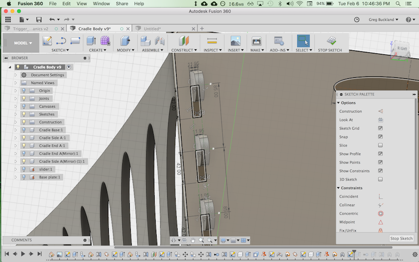
Using the geometry of the tabs as a visual guide, I sketched three slots on the face of the End in order to receive the tabs. I mirrored these slots across a center line, created an ellipsoid handle cutout, and the extruded all these shapes in a cut operation to cut them from the End.
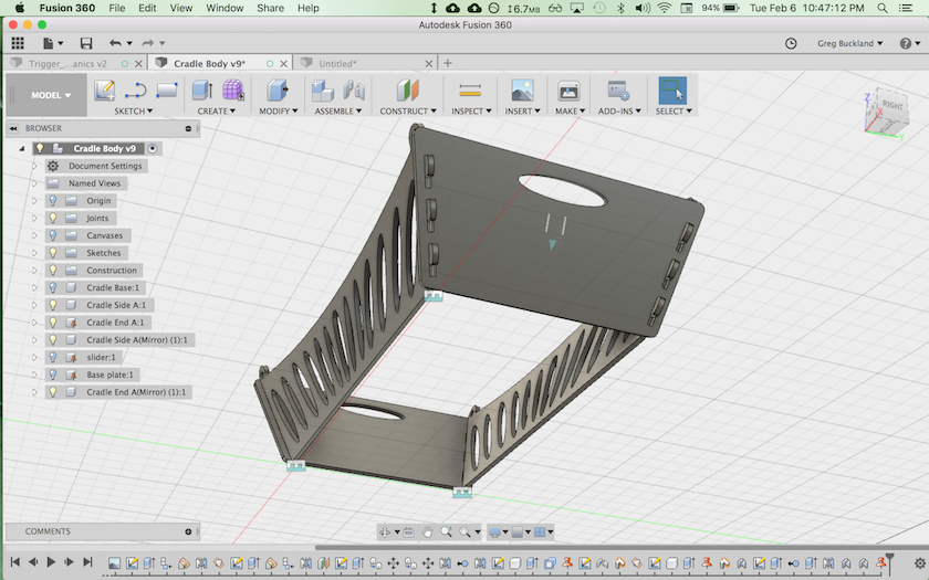
Once I got the Sides and the Ends correctly lined up, I created "as-built" rigid joints between all four pieces and "grounded" one of the Ends. This ensures that the pieces will remain in correct relationship to each other.
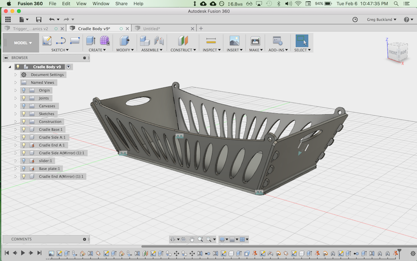
Making the base visible shows my CAD model so far. I still need to line up the base more precisely (currently, the lowest edges of the Side and End pieces overlap with the base geometry, which would cause a manufacturing error). I also still need to create more tabs (either on the bottoms of the Ends or the bottoms of the Sides) and receiver slots (in the base) to complete the connection between the four joined components and the base.
Conclusions
There is much more still to do, including CAD for the arm from which the cradle will hang. But for now, I have run out of time for this week.
Here is a link to my Fusion 360 design file (*.f3d)