Interface and Application Programming
Assignment
individual assignment:
- write an application that interfaces with an input &/or output device that you made
Firefly
I am going to try yo use a program called firefly that connectes the arduino environment to Grasshopper, allowing for live control of a microcontroller through Grasshopper and vice versa. Thought this sounded very interesting, so I downloaded and installed it, following the instructions layed out here
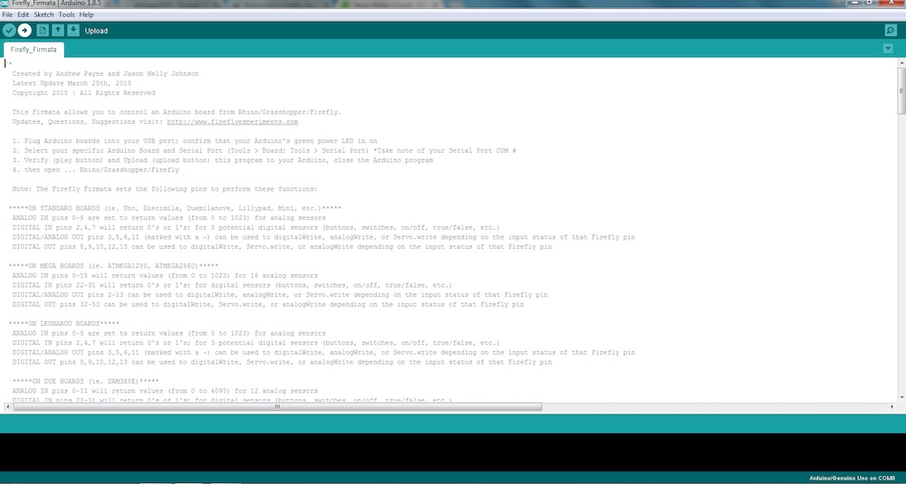
So the basic documentation for Firefly can be found here.
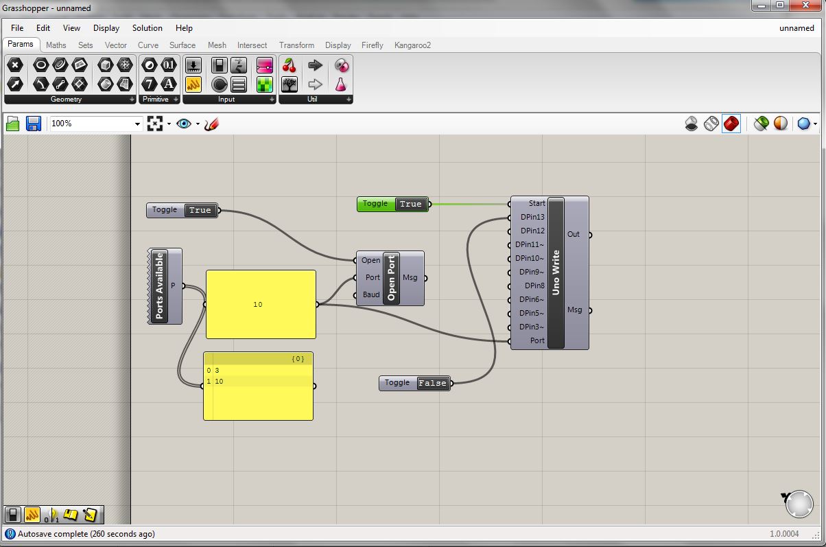
The first essential node to get the firefly interface up and running is the "Ports Available." The output is simply connected to a panel so we can see the results. From that we can see that ports 3 and 10 are available. I"m not sure if there is a definitive way of knowing which port is the one hooked up to the board without just trying to connect and see which one works. Anyway, I had just uploaded the Firmata firmware through Arduino IDE so I knew it was port 10. I created another panel containing "10" to input as the port variable on other nodes. Next we create the "Open Port" function. It has three inputs, the port (number 10), the baud (set to 9600 by default), and "open". The open variable takes a boolean state, true or false. If true, and the other inputs are properly selected, the port should open, creating a communication link between the board and the grasshopper interface. This set of modules really stand on their own and are simply to open communication. The next essential node is the "Uno Write" function. This function gives us access to digital pins 3-13 not including 4 or 7. Pins 11, 10, 9, 6, 5, and 3 have built in PWM capability as well as the standard High or Low, 0 or 1, true or false, boolean binary. Of course we are not using an arduino uno, but because we've programmed the satshakit board with the arduino bootloader, and it uses the same Atmega chip, everything works smoothly. I'm sure there is a way to dive a bit deeper and set up the firefly environment for other boards, but thats a bit beyone my reach right now. I just want to get a basic, proof of concept blink going to I know everything is working. To do this I create a boolean toggle and connect is to pin 13, which is attached to an LED. Indeed, when I toggled the button to true, the light turned on. I was surprised by how satisfying pressing this digital button and seeing a light on my board come on was.
Everything is very nicely laid out.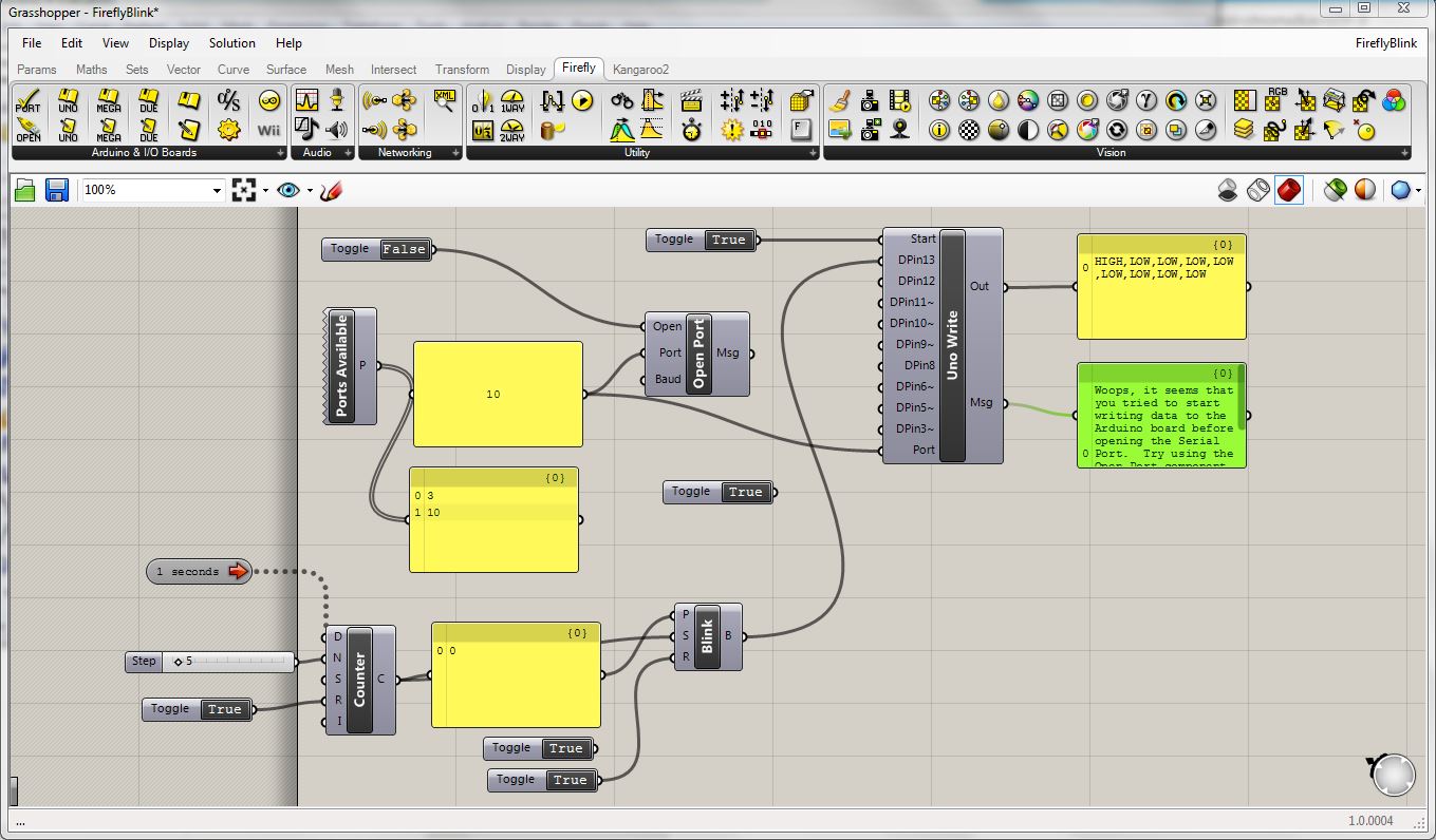
To download my files click here: