Exercise 15 Mechanical Design
Group Work
To see our group page, visit this link.
Personal Contribution
For our group project, I was tasked with designing accessories such as a knob and also for documenting the procedure we implemented and any issues we encountered. As you'll see, the part that I have documented for the accessories isn't very large because working on taking notes and pictures and overall documenting the group portion for both weeks was my primary contribution. I sketched then designed a knob in Tinkercad to turn one of the axles.
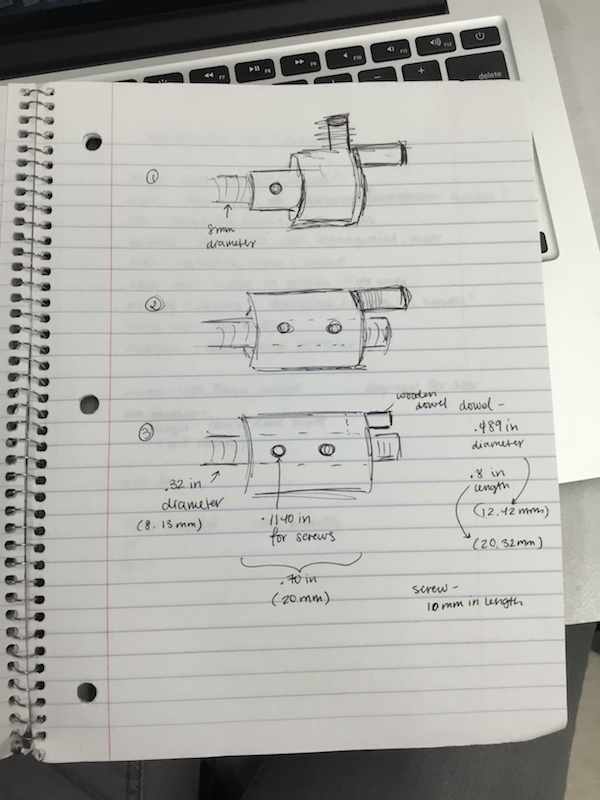
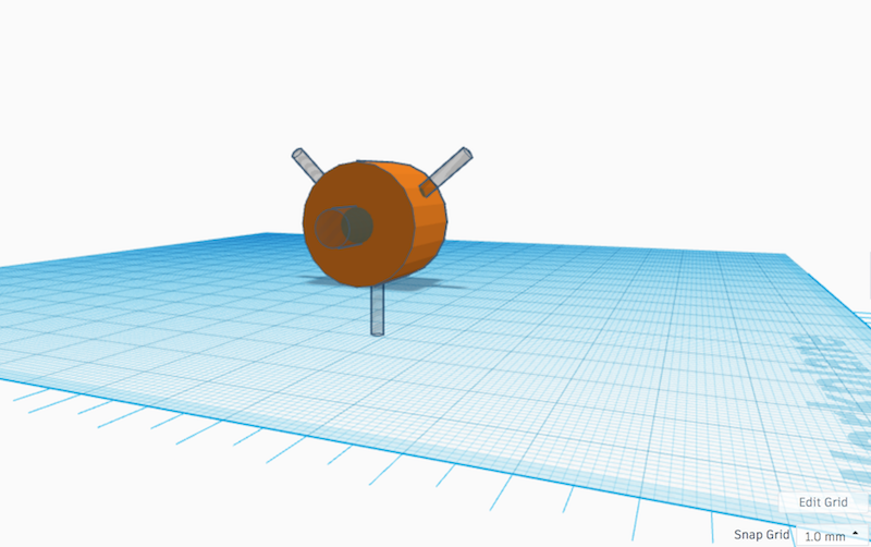
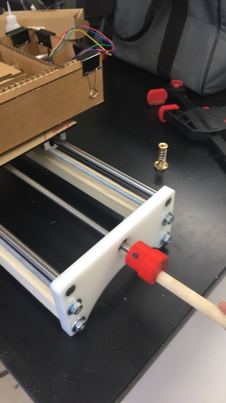
There are a few things I could do to improve my design. Firstly, I could increase the outer circle diameter so that there will be a larger rotation, hence making it even easier to turn the knob. Also, I could put increments in mm so we could measure how much the axis is being turned. Another thing that could be done is smoothing out the knob once it is printed and also attaching something more durable than a wooden dowel (something made of metal perhaps) and also glue the piece in, not just relying on the space where it fits. So there are multiple steps I could take to make the piece better to help the overall function of the machine.
To download all my files click here: