Exercise 04 Computer Controlled Cutting
Group Project: Characterization of the Laser Cutter
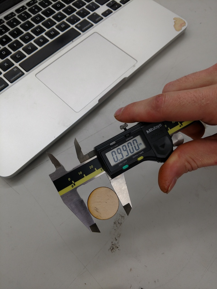
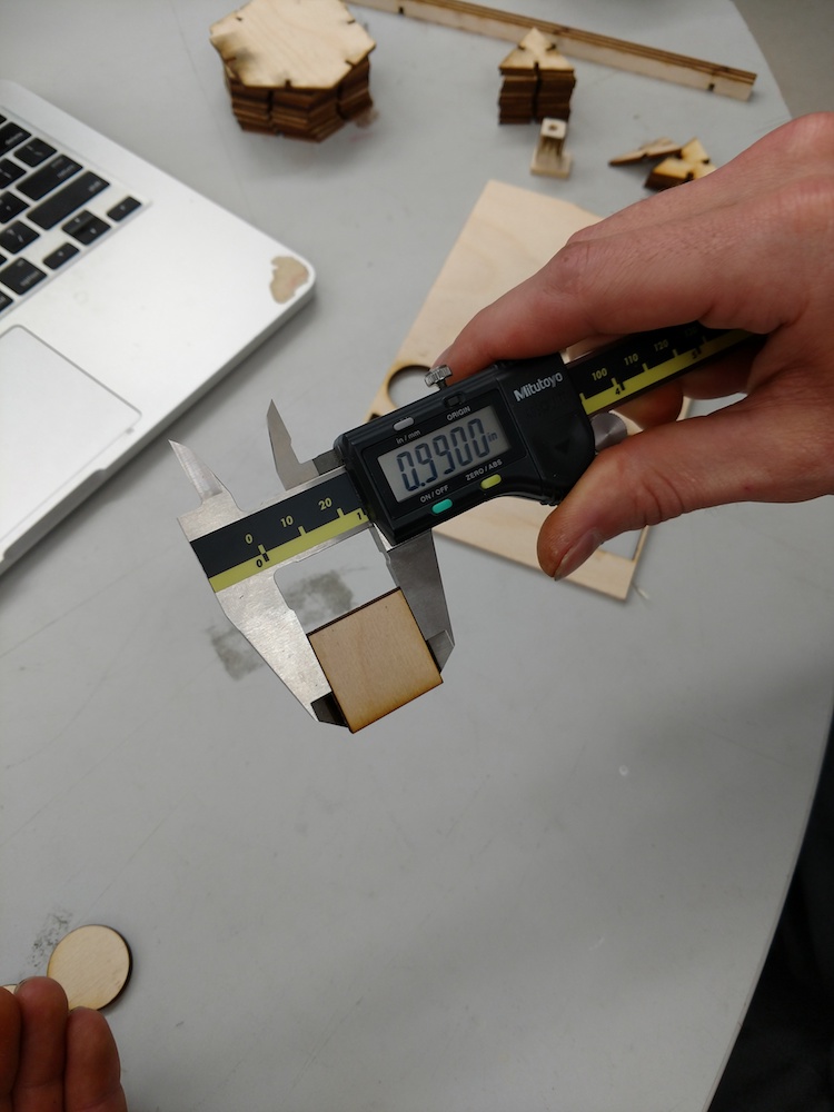
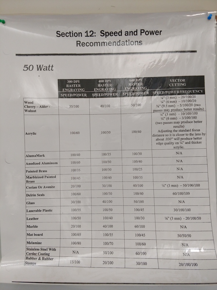
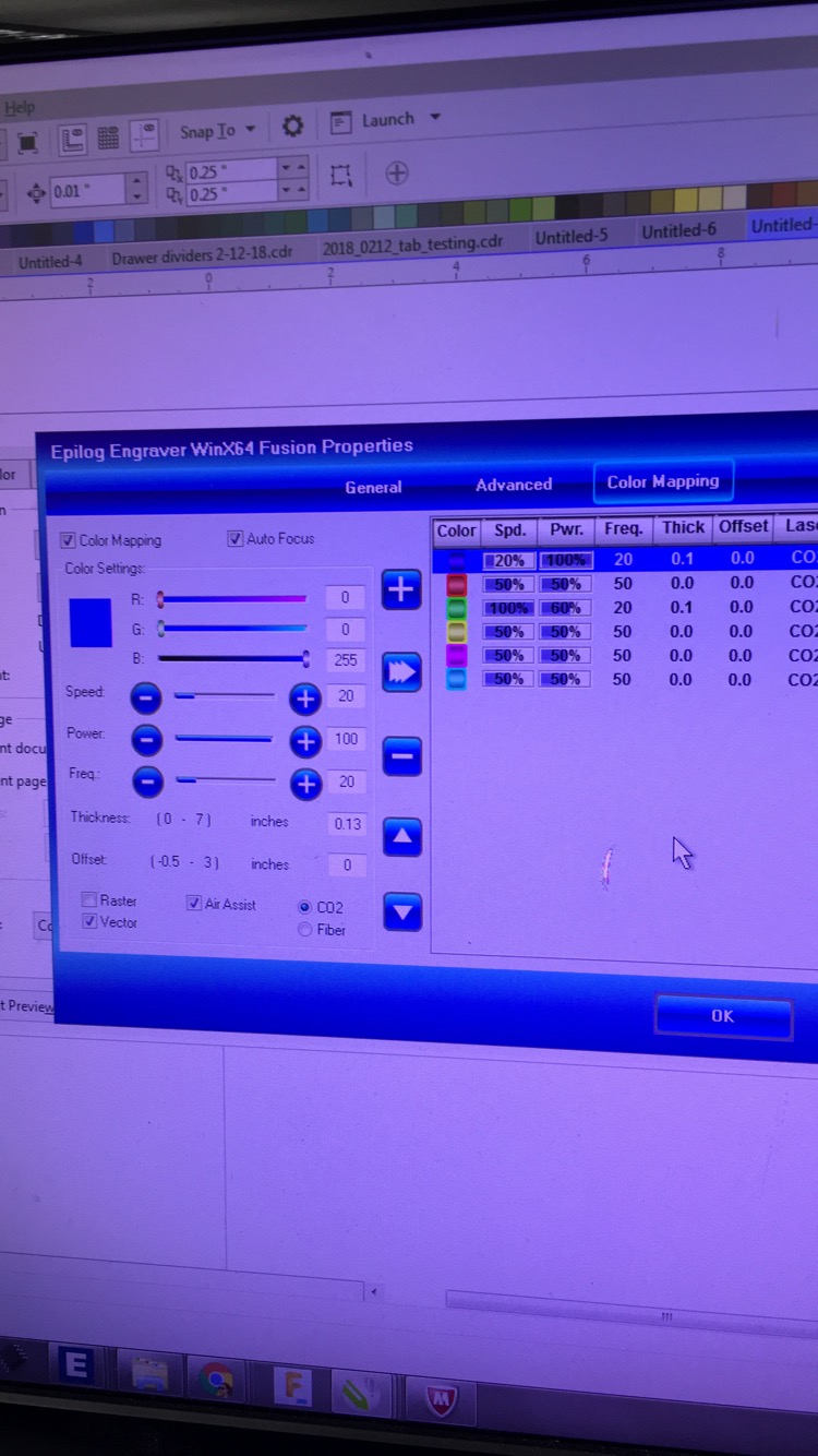
Our lab has an Epilog Laser Fusion M2 Cutter. To characterize our laser cutter we tested the tolerance on 1/8in ply wood. We designed a 1 inch square and 1 inch circle (both with black hairline stroke) in Corel Draw. From there we cut it out on the laser cutter. After measuring the shapes with a caliper, we found the measurements were .99 in instead of 1.0 in. So we know that to get precise measurements we have to make designs .01 more. We used the settings speed:5, power:100, frequency:20. We found that the speed was actually 5 units lower than the poster we have on our wall which calls for a speed of 10.
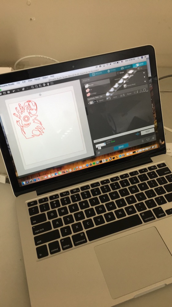
Vinyl Cut Design
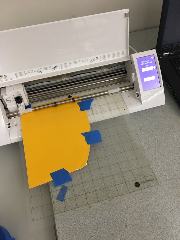
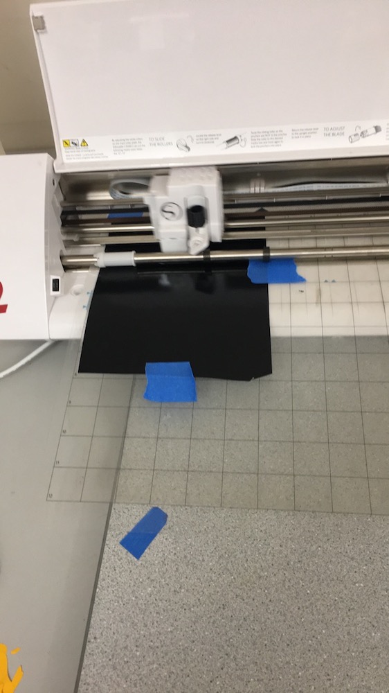
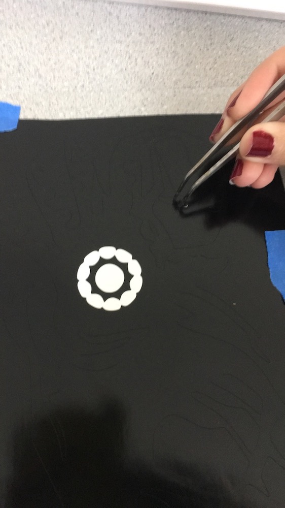
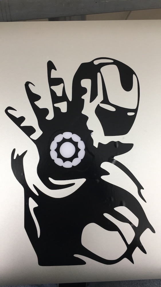
I used Silhouette Studio to create my design and cut it out on the Silhouette Cameo. I found a picture of iron man on google, took a screenshot, and uploaded it into Silhouette Studio. I then used the Trace function (that looks like a butterfly) and selected the area I wanted to cut. I then saved the file and attached my laptop to the cutter. I decided to do a test cut with some yellow vinyl so i cut a piece about 8 by 7 in and put it on the sticky mat. I then loaded the mat into the Cameo. From there I sent the cut to the Cameo from my laptop. The cut went smoothly. I used tweezers to remove the areas I didn't want to transfer to the surface I would be applying it to. Afterwards I applied the transfer tape to the vinyl and used a green flat tool to press it down. From there I used the transfer tape to move my vinyl design to my laptop. After being satisfied with the result, I repeated my process with black vinyl for my final product.
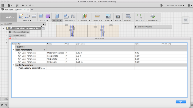
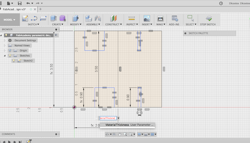
Parametric Design
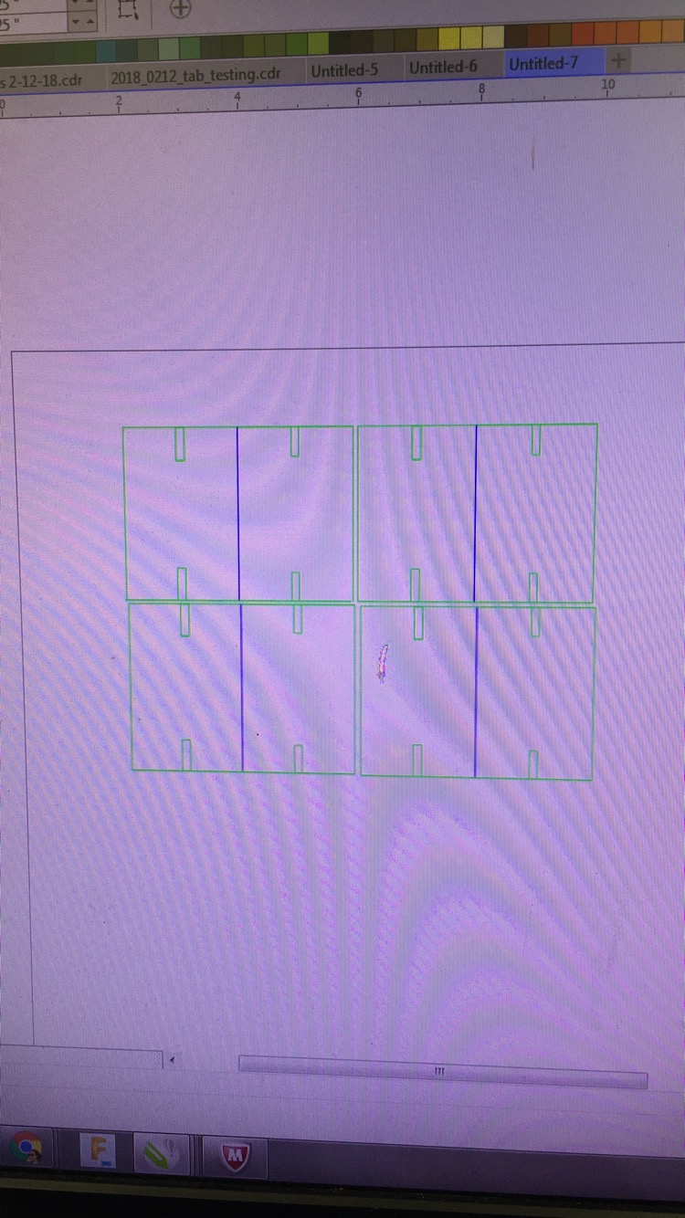
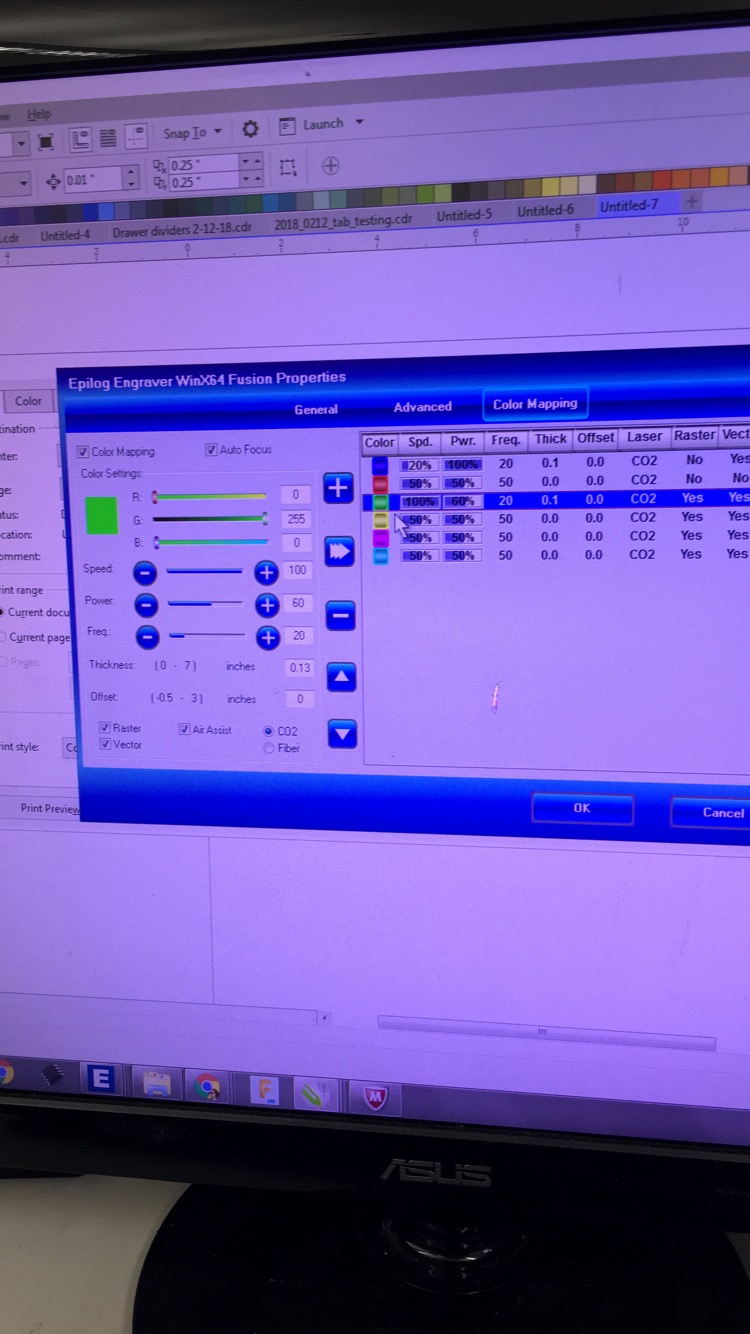
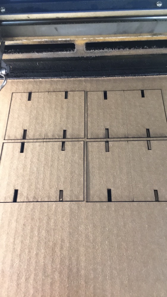
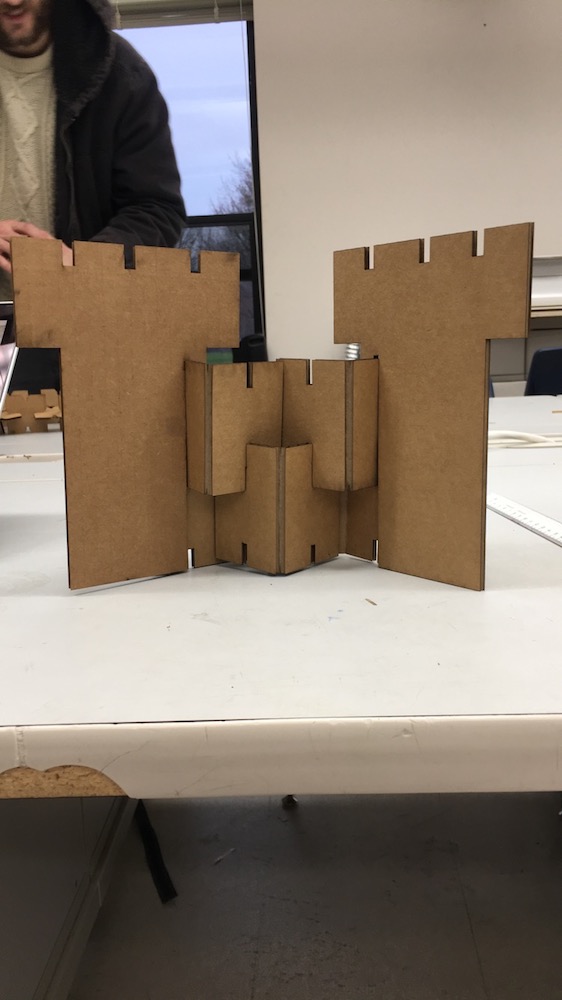
I experimented and learned about parametric design in Fusion 360. After watching an Autodesk Fusion 360 tutorial on parametric design, I experimented with some rectangles. After changing the units from mm to inches, I created a sketch in the XY plane with a width of 4 and height of 3. From there I drew a line down from the midpoint to create two separate rectangles. I then drew a line from the midpoint to either of the two sides (so created two lines total). I drew a center rectangle of width of .13, which is the thickness of cardboard, and height of 1, on the midpoint of each of these lines. I then used the trim tool to get rid of the rectangles protruding from the large rectangle. I made four of these small rectangles. From there I used the constrain functions such as equal to make the sides equal so when I changed one, it changed all of them. After this, I saved it as a DFX file and opened it in Corel Draw. From there I made sure all the lines had a hairline stroke. I also needed to use color mapping so the middle line would raster and the rest would cut. The middle line I made green while the rest was blue. I used speed:20, power:100, frequency:20 for the blue and speed:100, power:60, frequency:20 for the green. I also changed the thickness to .13 inches. I then cut out a few copies on the laser cutter. After putting the pieces together (they fit quite well!!) I decided it looked kind of like a castle wall so naturally decided to add some castle turrets. I designed the turret in Fusion 360 using parametric design and cut it out. It was much easier making the slots the second time I did it!
To download all my files click here: