Computer Controlled Machining
Design Files
- Side of Stand for Talking Puzzle in Fusion 360
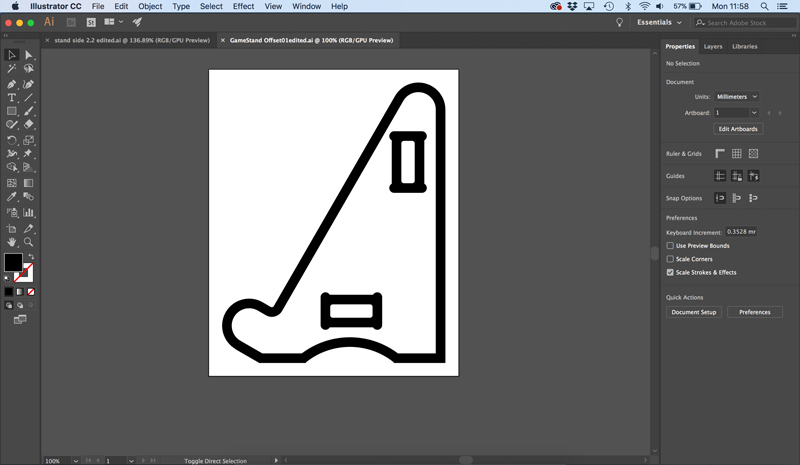
- Edited Side of Stand for Talking Puzzle in Adobe Illustrator
Group Assignment
We don’t have a large scale CNC machine in our lab so we were given limited access to an industrial CNC milling machine in a different department at the university. As I was only an observer on this course, rather than an official student at that point, and there wasn’t enough time for everyone to build something, I received the training but didn’t produce something. So to complete this assignment I was restricted in size by the limits of our labs milling machine. I am making a stand to put my Final Project on, from 18mm birch ply.
The instructions to use the CNC machine which we created as a group project, are available at:
https://docs.google.com/document/d/1nM3I74lo6kCKSXbm4yPZyP9x-JLXkAzlg__Yr2c2eGw/edit#heading=h.4fjlt0e5c9xs
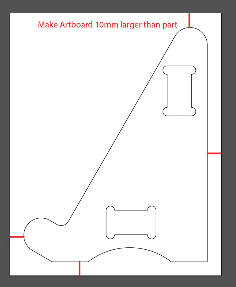
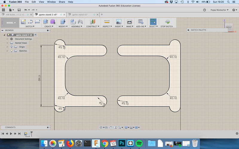
The milling machine can do a right angle when it cuts an edge on the outside of the material, but it wouldn’t create a right angle inside a slot because it’s a circular drill bit, so the edge would be curved. So I created circles that are the size of the drill bit plus 0.1mm and positioned them in the corners of the rectangular slots. There different ways to position the circles to make T bones and I chose to have one line of the rectangle at a tangent to the circle, making a cotton reel shape.
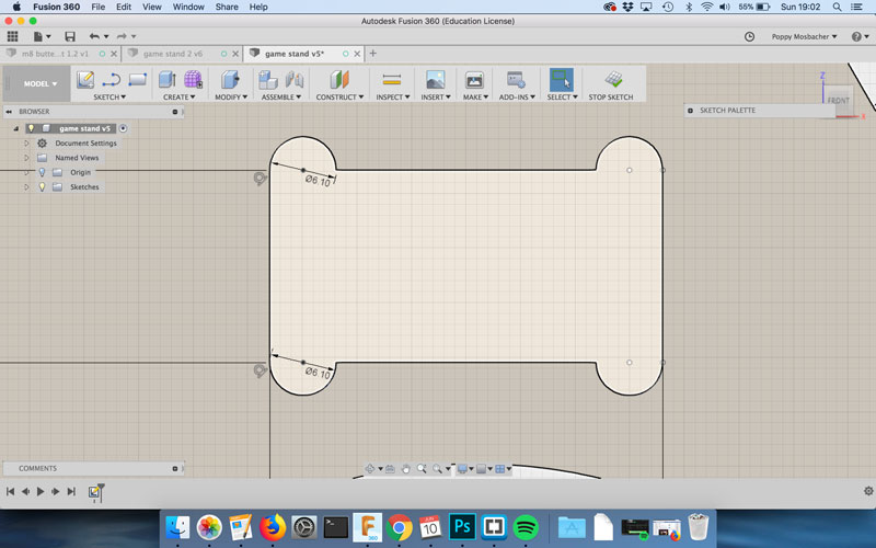
The thickness of the wood ranged from 17.6 - 18mm, so the distance for the slot was 17.6mm because it wants to be a secure fit. Pieces can be hammered in place or sanded, which is easier than adding material.
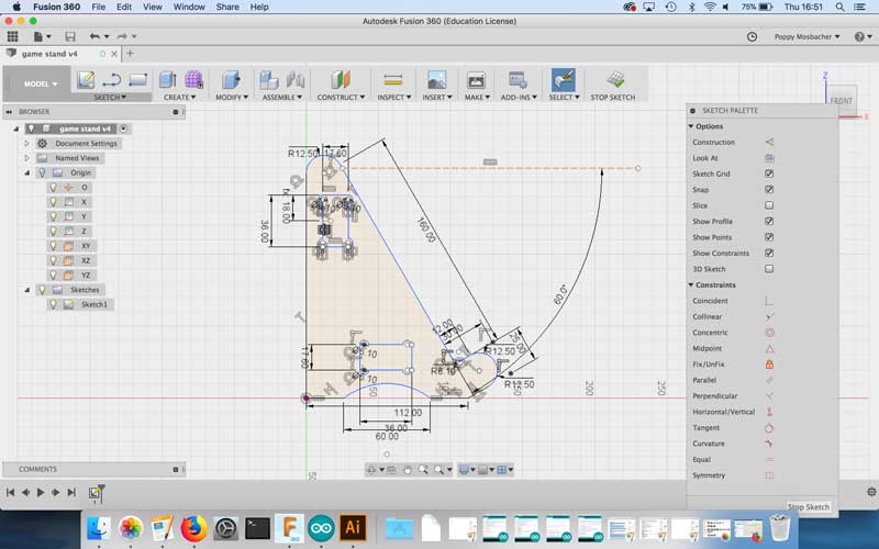
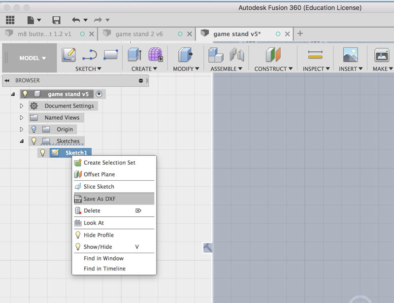
I saved the design as a DXF by right clicking on the Sketch in the Browser tree, shown below.
I then opened the DXF in Adobe Illustrator to get the file ready to be processed by FabModules, shown in the images below. This involved changing the artboard size to be 10mm larger than the design to avoid wasting material, and updating the colours for FabModules to understand where to cut. This involved joining the outline into one continuos path, by selecting it and going to Object > Path > Join, so I could use the fill tool. I then saved the file as PNG, which is the format FabModules needs to create the cutting path.
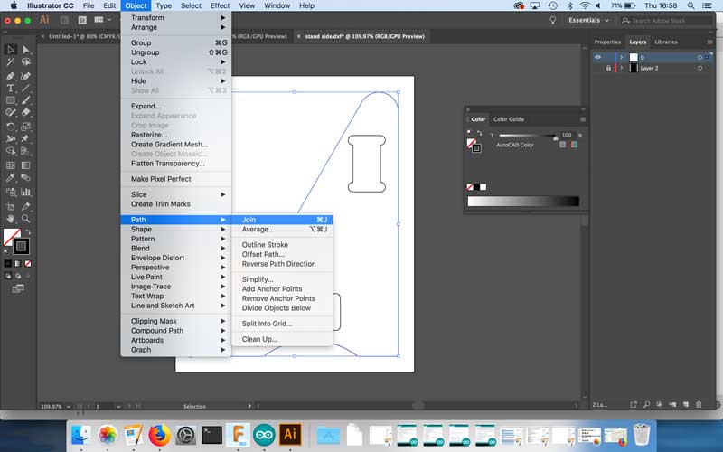
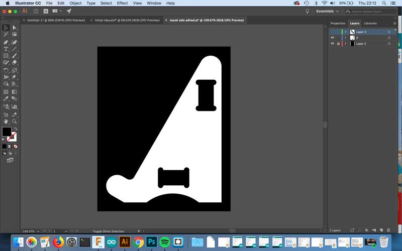
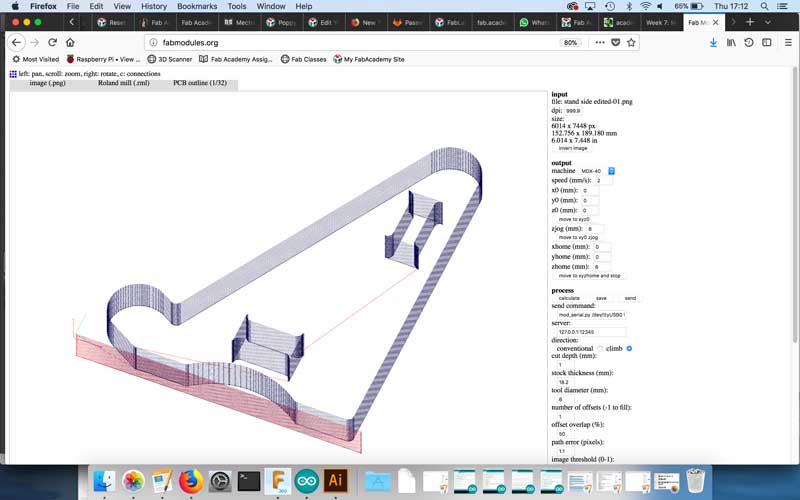
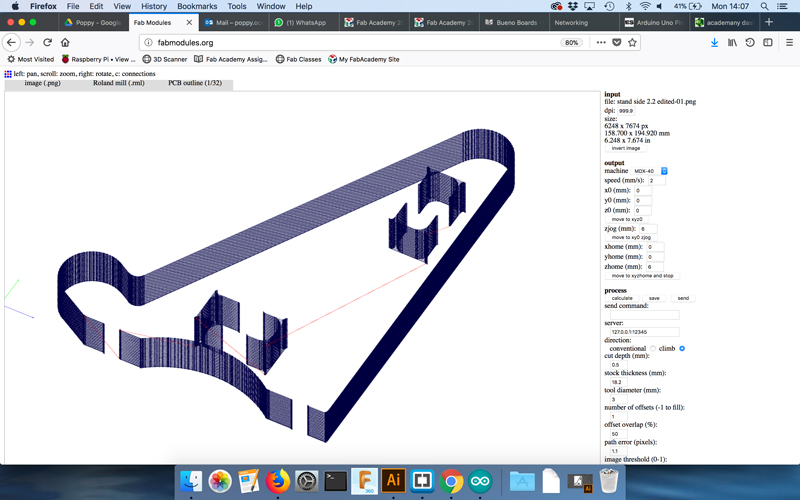
At first I used fabmodules to set the cutting path with a 6mm tool and a cut depth of 1mm, as shown above. This means it goes down 1mm on the first round and and then 1mm the next and so on. Therefore it would take 18 goes to cut through the whole sheet of wood. However, the wood was turning black during the cutting, which means it was burning and the waste coming off looked like burnt toast crumbs. This was overcome by increasing the spindle speed and decreasing the xyz speed.
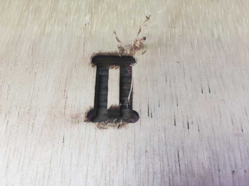
Part way through, the machine stopped moving, the lights turned red and error message came up saying the spindle experienced overcurrent.
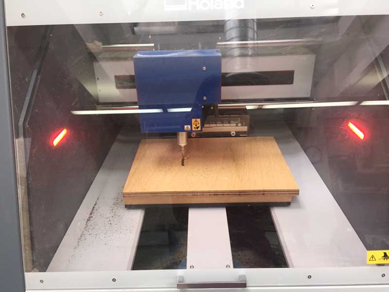

The 6mm drill bit had too much torque, so in Fabmodules I updated the cutting path to work with a 3mm drill bit, going down 0.5mm at a time instead of 1mm. This was better, as shown in the video below. The 3mm drill bit removes less material per pass compared to the 6mm therefore there is less friction.
These are the successful fabmodule settings for the first side of the stand:
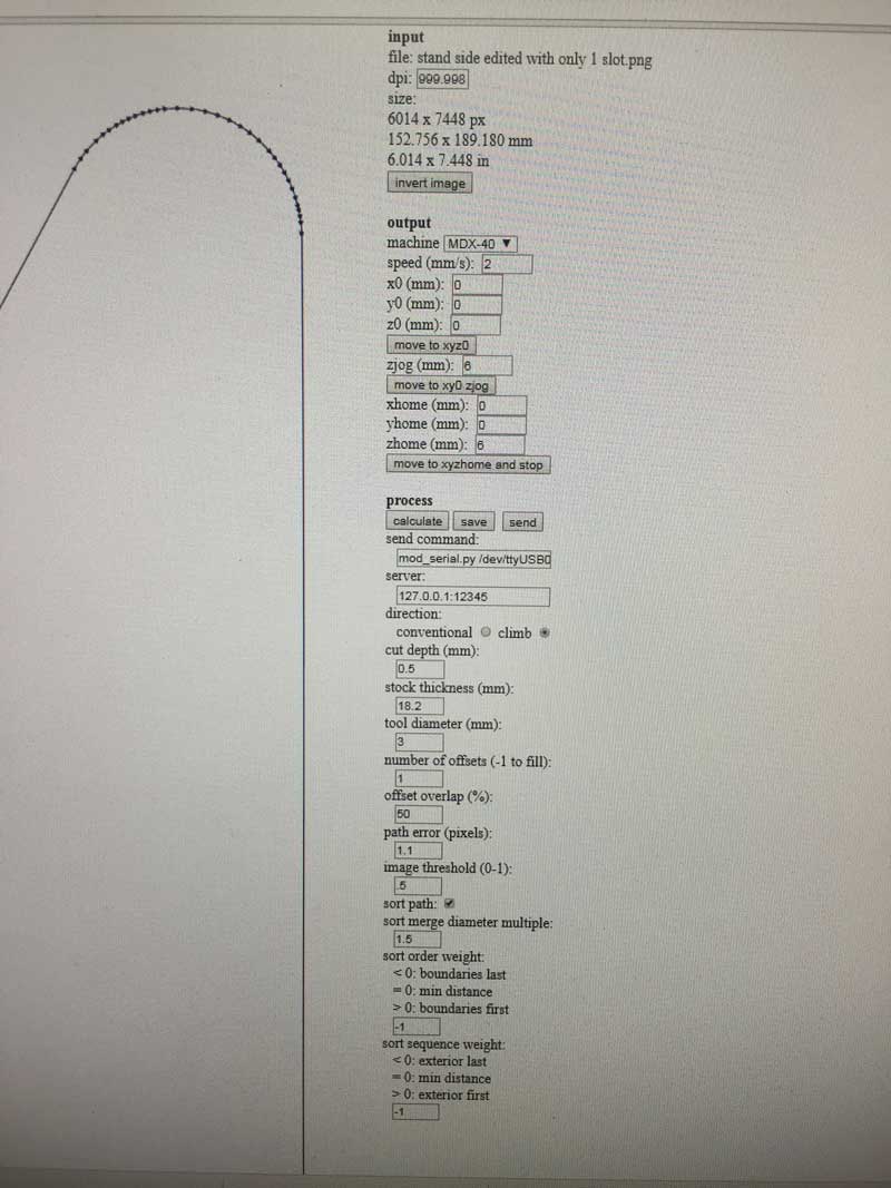
For the first side of the stand, I didn’t use tabs because I secured the wood to the sacrificial wood using double sided sticky tape, but the tape wasn’t in the right area, so the waste material moved once it had finished being cut and caught the drill bit. So I opened the machine, removed the waste material, went back to my PNG file and in photoshop drew a black rectangle over the slot that had already been cut, then remade the cutting file in Fabmodels so that it would start on the next slot. Redid that again for the next one. The machine automatically stopped when the waste material was in its way.
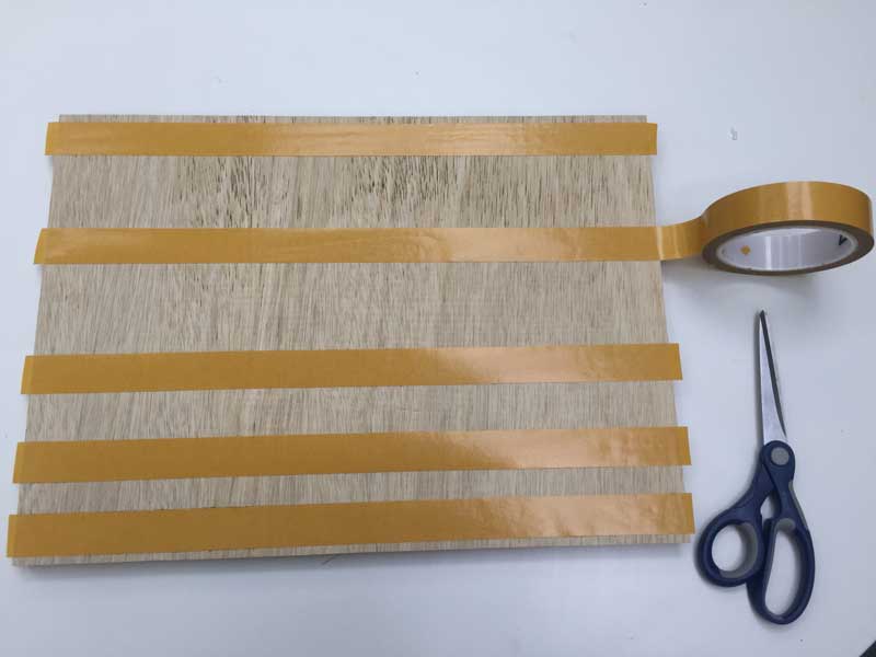
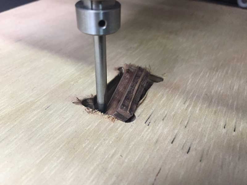
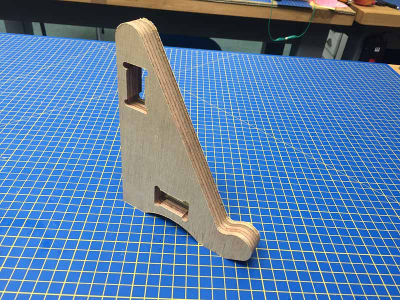
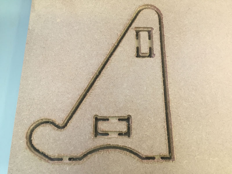
The first side of the stand was successful, as shown above, but before cutting the next side of, I added tabs to the slots, as shown below. By then I was using a 3mm drill bit, so I resized the T bones to have 3.1mm circles instead of 6.1mm.
The machine kept stopping, so I tried different speeds for the spindle and the xyz movement. I found out the problem was that the drill bit was too short, It would stop when it had 3mm left to mill. I recreated the cutting file in FabModules to cut 3.5mm, with settings for a 3mm drill bit but actually used a 6mm drill bit to cut down the first 3mm, shown below. The idea was to then change back to the 3mm bit and to mill through the air for the first 3mm that had already been cut, because then there would be a trough to give the drill bit more space. Unfortunately, someone else needed to use the machine before I had finished and I lost the point of origin, so I had to start again. This time I am going to use MDF which is softer and may not have the torque issues.
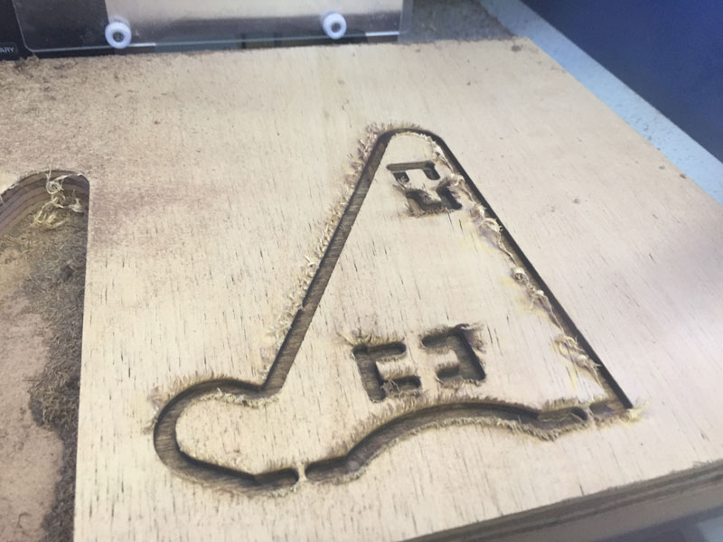
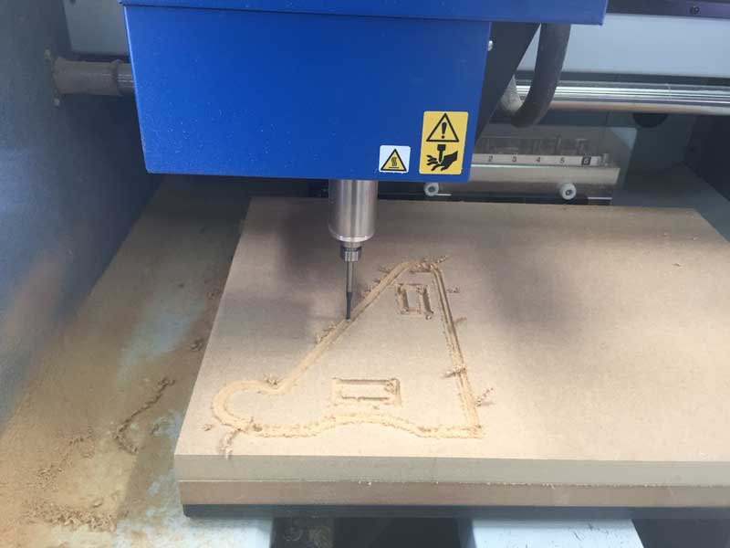
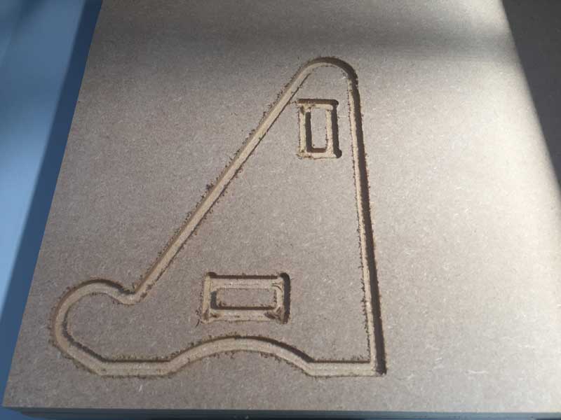
Instead of using a 6mm drill bit to cut the first 3mm of the MDF, I used a cutting path that was offset to the original by 1.5mm in both directions, shown in the photos below. It wasn't necessary to have the tabs for this stage because it's not cutting all the way through, so the path could be continuous. This workaround of cutting the first 3mm wider is not ideal, because it means during the proper cut there is a lot of time just milling through air. In total it took about 7 hours to cut the piece.
I used the same fabmodules settings as the plywood for the MDF, as shown below, and started with a spindle speed of 13000, but ended up overiding the speed to 200% when it was clear it was working.
The image below shows the second side of the stand once the milling was complete. The tabs worked, because the piece is secured in place. Next step is to cut the tabs off.
