3D Printing and 3D Scanning
Design Files
- Chainmail Fusion360 File
- Chainmail.stl
- Due to online privacy, 3D scanning design files are available on request for FabAcademy assessors
Group Assignment
I knew a lot about 3D printing and scanning already, having made a RepRap Prusa Mendel 2 3D printer, taught people how to do 3D printing at uni and Glastonbury Festival, produced the 3D printing guide for Product Design students at Brighton uni and helped design and build a 3D body scanner using Raspberry Pis. So for this weeks assignment I produced a video resource for designing interlocking parts to 3D print and published it as an Instructable here. The video shows every detail for a beginner of Fusion 360 to follow and has a voice over to make it clearer. I personally didn't experience problems doing 3D printing or scanning in this weeks task, buy I tested my video on a complete beginner and added time referenced tips, to resolves problems that she experienced during the testing.
Extra Tips for Anyone New to Fusion 360
The times below are points in the video where beginners might need extra clarity:
This project demonstrates many Fusion 360 techniques. It starts with creating and extruding a flat image to make a simple 3D shape, and quickly progresses to making repeating interlocked patterns that can be printed in one go. This wouldn't be possible with a subtractive technique, because the tool wouldn't be able to reach the inner parts.
3D Model
Rotate or zoom in on this model with a mouse/trackpad.
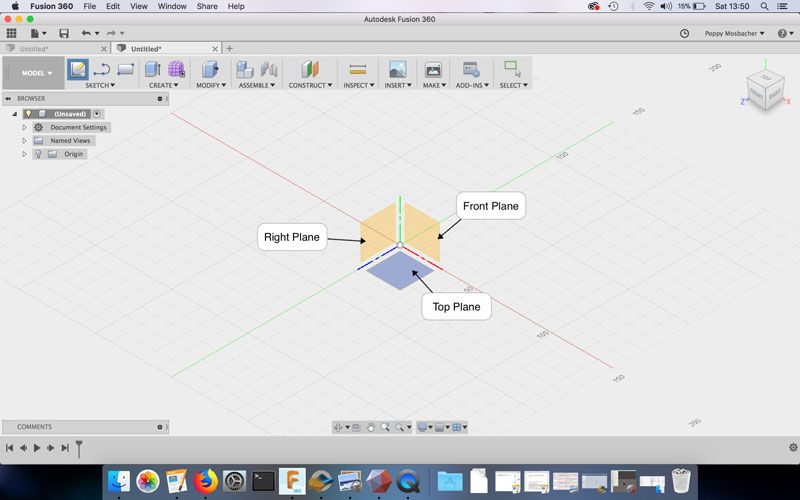
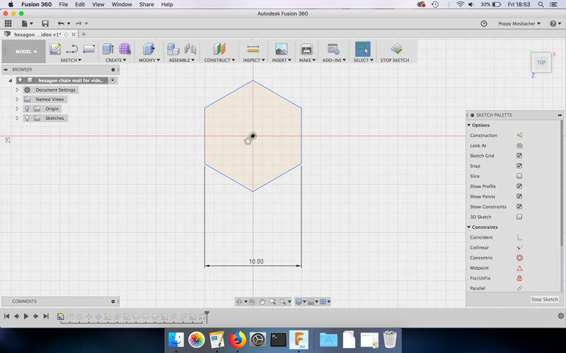
Step 1: Create a Hexagon
- Create Sketch on the top plane.
- Go to Sketch - Polygon - Circumscribed Polygon and choose 6 sides to draw a hexagon.
- In Smart Dimension set the hexagon length to 10mm
- Go to Create - Extrude and extrude the hexagon by 1.2mm (this will also Exit The Sketch)
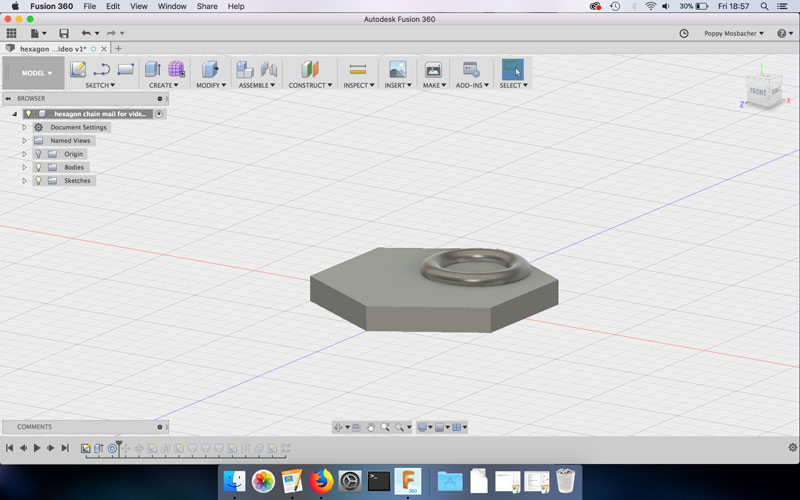
Step 2: Create the Rings
- Go to Create - Torus and choose the surface of the hexagon as the plane to draw on.
- In the Torus box, choose the following settings:
- Inner diameter: 4.2mm, Torus diameter: 1mm, Operation: New Body
- Go to Modify - Move/Copy
- Rotate the Torus by 90 degrees. Don't click OK yet, because there's more moving to do.
- Position the Torus at an edge of the hexagon, using the View Cube to look at it from different angles.
- Rotate the Torus by an extra 30 degrees and reposition it at the edge of the hexagon. Then click OK.
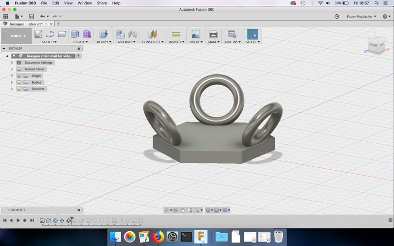
- Go to Create - Circular Pattern and choose the following settings: Object: Torus, Axis: Y (green line), Quantity: 3
Step 3: Create the Poles
- Go to Create Sketch and choose the surface of the hexagon as the plane to draw on.
- Go to Sketch - Circle - Center Diameter Circle and draw a circle with a diameter of 2.5mm.
- Draw a construction line from the center of the hexagon to the center of one of the hexagon edges.
- Press Shift (on the keyboard) + click on the center of the circle and the construction line, then select the Coincident constraint in the Sketch Palette.
- Press Shift + click on the perimeter of the circle and the edge of the hexagon, then select the Tangent constraint.
- Go to Sketch - Circular Pattern and choose the following settings: Object: Circle, Center point: Center of hexagon, Quantity: 3
- Then click Stop Sketch
- Go to Construct - Offset Plane to create a construction plane. Choose: Plane: Top surface of hexagon, Distance: 3.2mm
- Go to Create Sketch and choose the construction plane to draw on.
- Sketch a circle, as before, with a diameter of 2.5mm. Position the new circle in line with a previous circle and Smart Dimension the centers to be 3.25mm apart.
- Go to Sketch - Circular Pattern, Object: The new circle, Center point: Center of hexagon, Quantity: 3
- Then click Stop Sketch
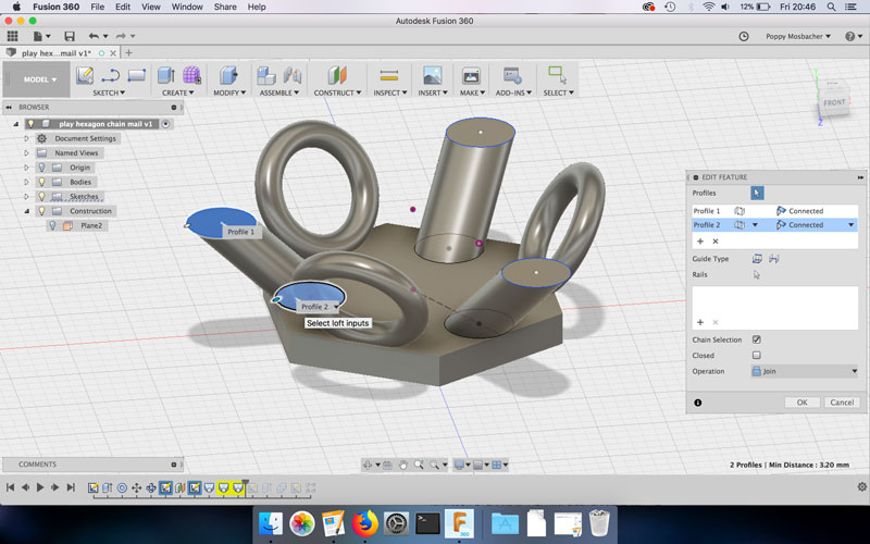
- Go to Create - Loft for each pair of circles. Note: if the circles are not visible, click the light bulb icon on the appropriate sketches in the Browser tree.
- Go to Create Sketch and choose the top of the pole as the plane to draw on.
- Go to Sketch - Circle - Center Diameter Circle and click on the center of the top of the pole to be the center of the new circle. This will create a Concentric constraint. Make the diameter of the circle 3.3mm
- Go to Sketch - Circluar Patttern, Object: The 3.3mm diameter circle, Center point: Center of hexagon, Quantity: 3
- Go to Create - Extrude and extrude the 3x latest circles by 0.3mm (this will also Exit The Sketch)
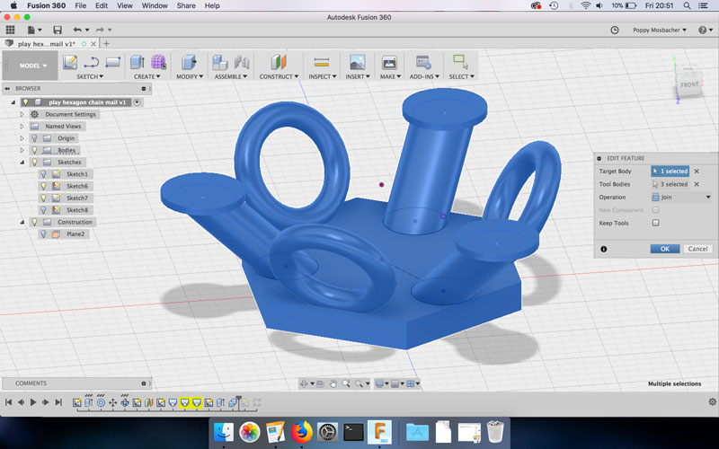
Step 4: Join Everything Together
- Click and drag the cursor around the model to select everything (the selected parts will be shown as blue)
- Go to Modify - Combine
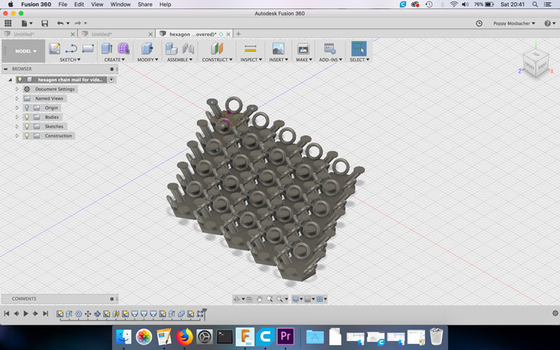
Step 5: Create a Repeating Pattern
- Go to Create Sketch and choose the top plane as the plane to draw on.
- Go to Line and draw a line from the center of the model through the center of one of the poles. Press Escape (on the keyboard) to end the line and select Construction in the Sketch Palette. (This creates a construction line that will not show up on the print). Create another construction line at a 60 degree angle from the previous line, which goes through the center of one of the rings.
- Then click Stop Sketch
- Go to Create - Pattern - Rectangular Pattern and choose: Object: Drag cursor around model, Directions: Select both construction lines, Distance type: Spacing, Quantity: As desired, Distance: 11mm
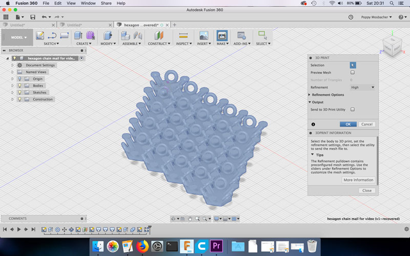
Step 6: 3D Printing
- Go to Make - 3D print.
- Select the whole model and choose the refinement quality, I went for high. Untick Send to 3D Print Utility.
- Name the file, choose where to save it and click Save. This creates an .STL file.
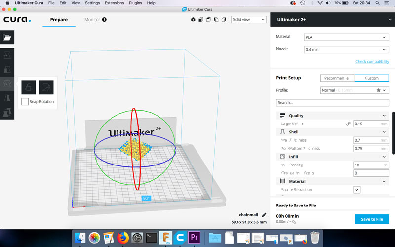
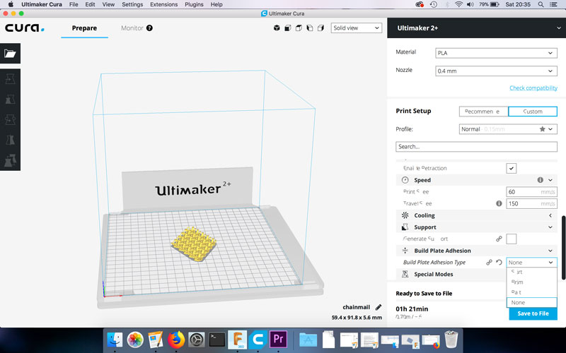
- Using Cura or another slicing software, open the .STL file.
- Rotate the model if necessary and click Lay Flat.
- Choose your settings (I used the default settings of my printer, except for changing the build plate adhesion from brim to none).
- Then Save as a gcode file.
- Insert an SD card into the computer and Save to Removable Drive. Then click Eject.
- Remove the SD card from the computer, insert the card into the 3D printer.
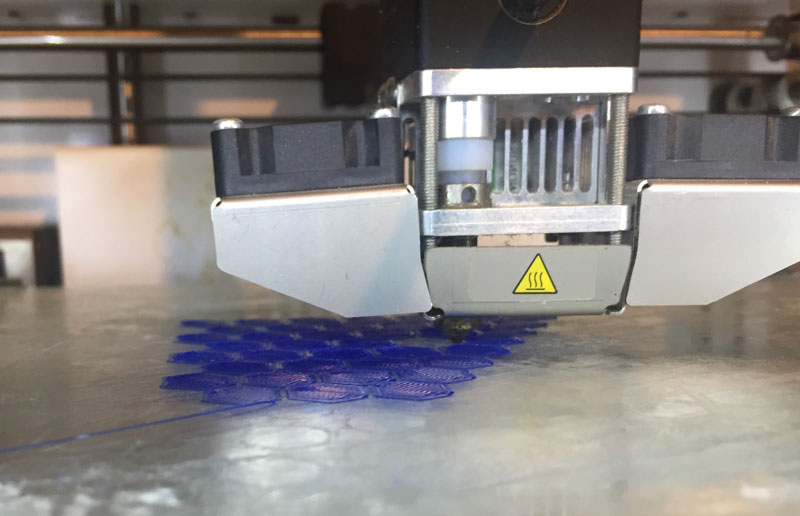
- Set up the 3D printer following the instructions for your machine and print the hexagon chainmail.
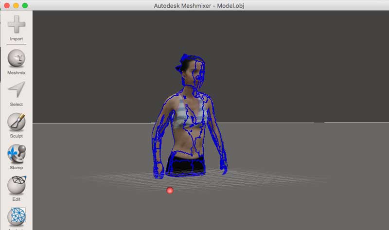
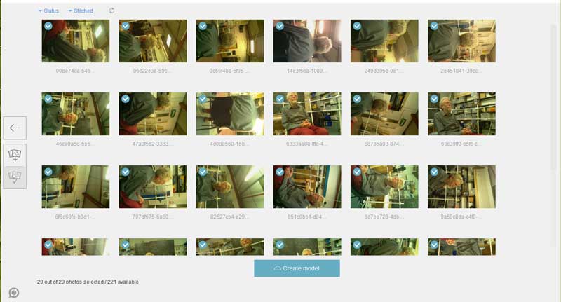
3D scanning
I took the images below using the 3D body scanner I made with Raspberry Pi cameras. The video underneath shows the result after applying photogrammetry software Autodesk Remake.
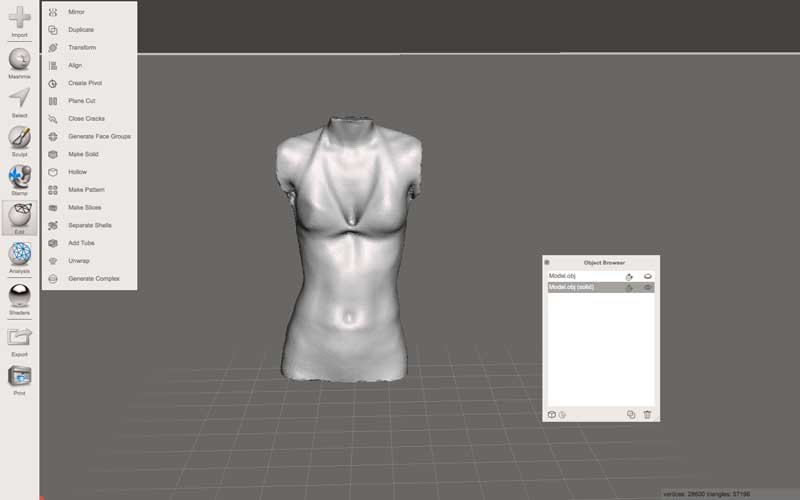
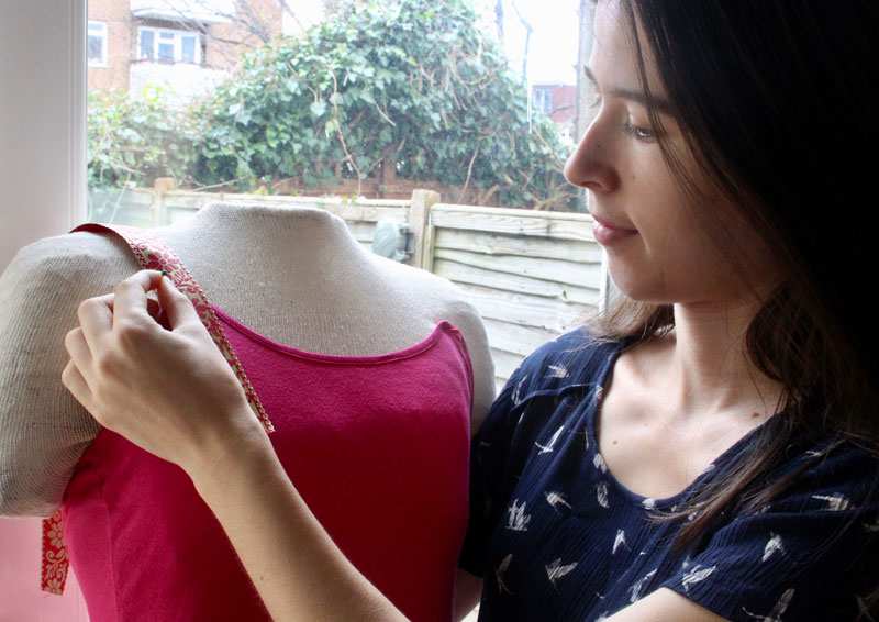
I was also scanned in the FabLab and I edited it in Autodesk Meshmixer. I removed my head and arms so I could use the scan to make a dressmakers dummy.