Electronics Production: Making an In-Circuit Programmer
Design Files
Group Assignment
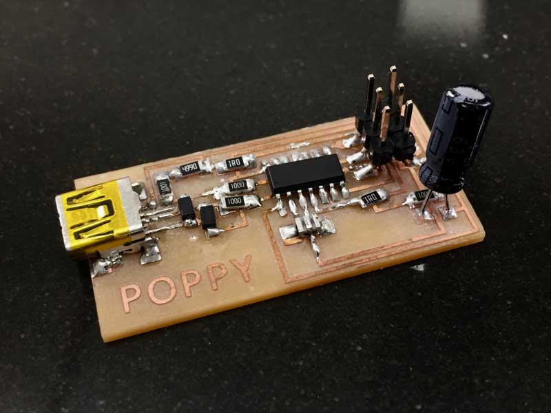
Arduino’s and other microcontrollers come pre-programmed to accept code and be recognized by the computer. When making your own microcontroller, you need to programme this yourself. You can either buy a programmer or make your own which is shown below.
Customising the circuit board file
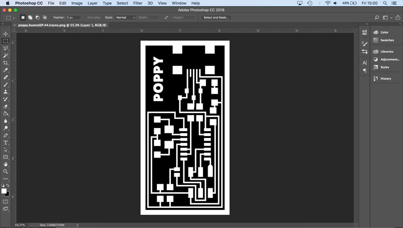
- Open the example board in Photoshop. (I used the one by my instructor, Luiz)
- Remove the current logo by drawing a black rectangle over the top of it.
- Using the text tool, type your name (or create a logo with the drawing tools)
- Change the text fill colour to white and the text outline colour to black (or white to make the text appear bold)
- Save the file as a PNG
Converting the file for the milling machine
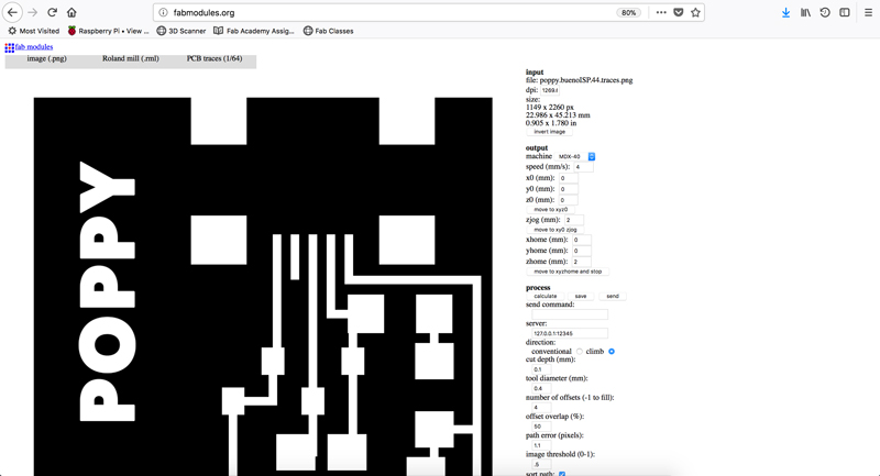
- In a web browser go to fabmodules.org
- Under Input format choose image (.png)
- Find the PNG file that was saved in the previous step and click Open.
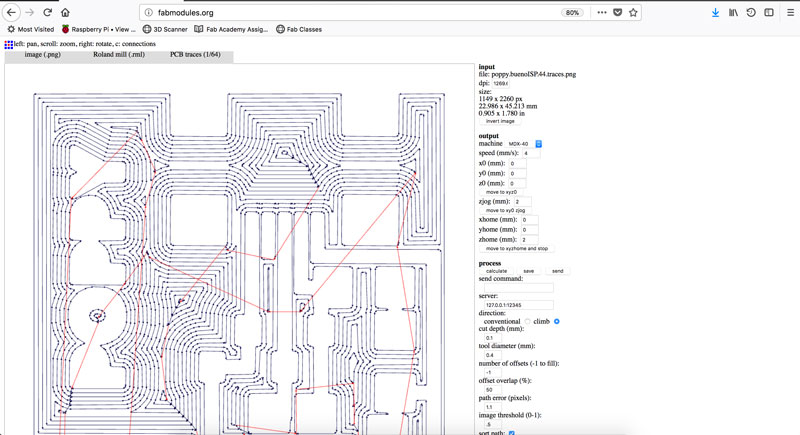
- Under Output format choose Roland mill (.rml)
- In the Output options on the right hand side of screen
Milling the board
- Select a piece of copper board that will fit the design
- Make sure it is flat by laying it on the its edge on a flat surface. If not, bend until flat.
- Apply double sided tape to the back of the board
- Stick the board to the sacrificial material in the milling machine. If possible, overlap the edge by a few mm to make it easier to remove after.
- Wipe the top of the board, applying pressure to make sure it sticks well and to clean it.
- Move the X and Y axis to the bottom left hand side of the board
- Hold down the Origin button whilst X and Y are selected in turn, until it updates to 0.0mm.
- Bring the Z axis close to the copper board, going down to 10x speed rate before getting too close. Otherwise the tool may move down too far and crash.
- Turn the Spindle on and set the speed at 10,000
- Lower the Z axis until the sound changes and it meets the copper board. Go down about 0.2mm more to make a small indent in the copper.
- Press and hold the Origin button while the Z axis is selected.
- Bring the Z axis up
- Open the .rml file (created in fabmodules) in the milling machine software
- To start the machine, click Output (Warning - this will start the machine immediatly, there is no confirmation pop-up)
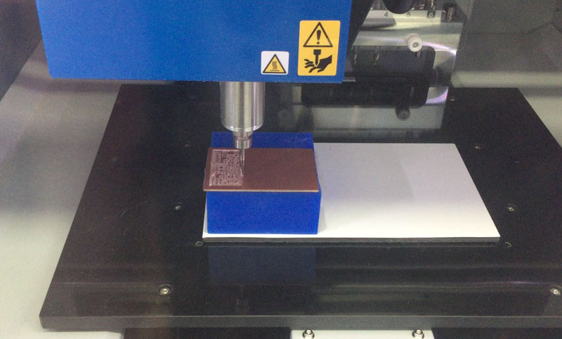
Soldering the board (called Stuffing)
This is the first time I've done surface mounted soldering so I used this video to get some tips:
Most of the Surface Mounted (SMD) components hadn’t arrived in time for this weeks tasks, so I used through hole components. There were no holes in the board, so I soldered the components on to the pads as if to do surface mounting.
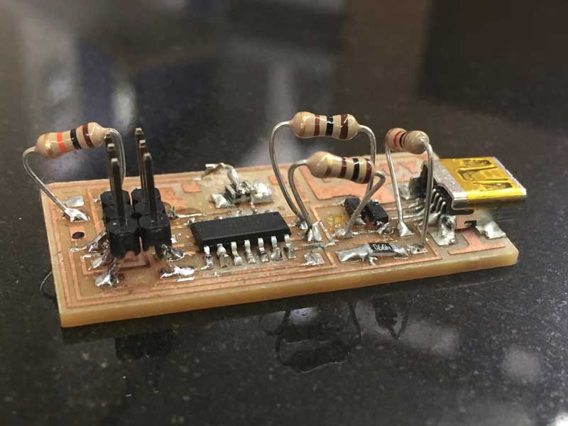
When the SMD components arrived, I remade the board and with the extra practice managed to do the soldering neater.

The resonator didn’t fit the first board, so I removed some pads with a craft knife and used wire to connect to the centre pad on the resonator - messy but it worked. On the next board I edited the traces to fit the resonator.
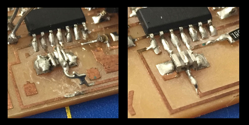
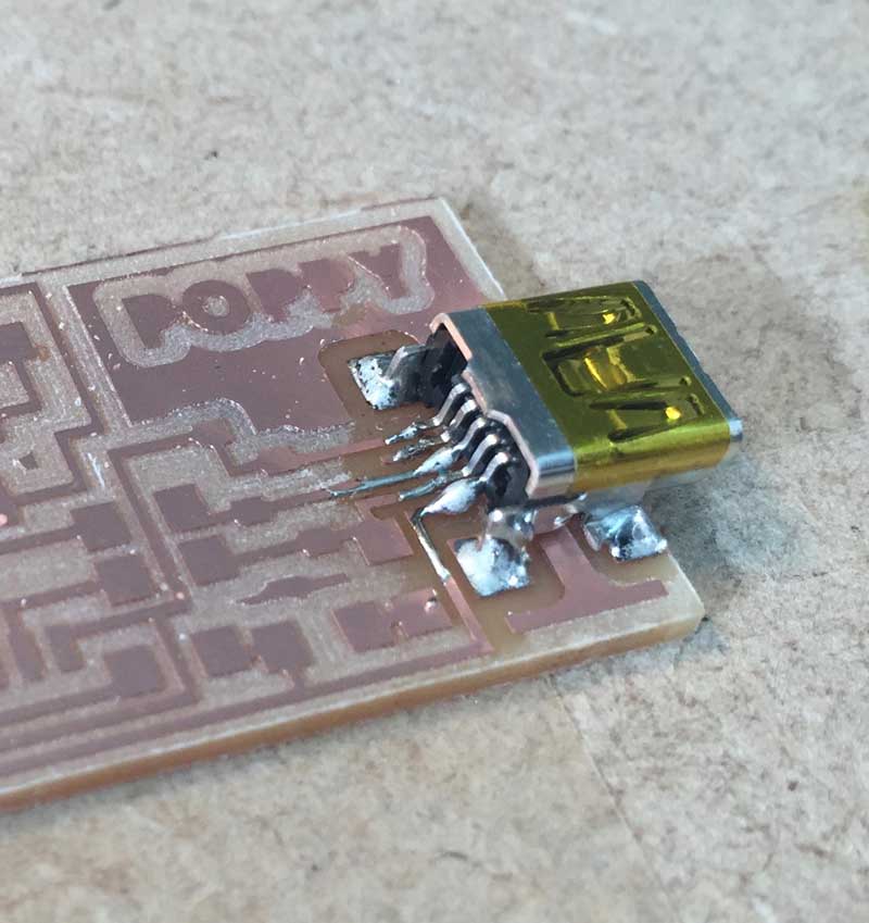
It was fiddly to get to the connections of the Micro USB plug, so I snapped off the back plate with pliers. Also removed the two locator pins underneath the plug with pliers, so it lay flat on the board. I shorted two of the pins on the Micro USB plug and used desoldering braid to remove. It was very fiddly.
Programming the board
This step is based on the instructions from http://archive.fabacademy.org/archives/2016/doc/programming_FabISP.html. (I'm using the Mac operating system but there are also instructions for Windows and Ubuntu and earlier versions of MacOS).
- Install CrossPack AVR
- Install XCode
- Download the firmware for Mac0S 10.8.2 or later to your desktop
Open Terminal and locate the folder that the firmware is saved in:
cd ~/Desktop/Unzip the firmware:
unzip fabISP_mac.0.8.2_firmware.zipOpen the unzipped folder:
cd ~/Desktop/firmware- Plug the board into the computer with a USB cable
- Attach the board to another programmer using a 6-pin programming header.
Open the MakeFile in a text editor. Edit the following two lines ...
- #AVRDUDE = avrdude -c usbtiny -p $(DEVICE) # edit this line for your programmer
- AVRDUDE = avrdude -c avrisp2 -P usb -p $(DEVICE) # edit this line for your programmer
... by removing the "#" at the beginning of the line with "usbtiny" in it and adding a "#" to the beginning of the line with "avrisp2" in it.
Save the Makefile
Programming the boardIn terminal locate the firmware. The following command is if the firmware is saved on the desktop:
cd Desktop/fabISP_mac.0.8.2_firmwareCompile the firmware:
make cleanIf successful, you will get this response:
Type:
make hexIf successful, you will get this response:
[ln-mowifi-02-10:fabISP_mac.0.8.2_firmware poppy-laptop$ make hex
avr-gcc -Wall -Os -DF_CPU=20000000	 -Iusbdrv -I. -DDEBUG_LEVEL=0
-mmcu=attiny44 -c usbdrv/usbdrv.c -o usbdrv/usbdrv.o
avr-gcc -Wall -Os -DF_CPU=20000000	 -Iusbdrv -I. -DDEBUG_LEVEL=0
-mmcu=attiny44 -x assembler-with-cpp -c usbdrv/usbdrvasm.S -o usbdrv/usbdrvasm.o
avr-gcc -Wall -Os -DF_CPU=20000000	 -Iusbdrv -I. -DDEBUG_LEVEL=0
-mmcu=attiny44 -c usbdrv/oddebug.c -o usbdrv/oddebug.o
avr-gcc -Wall -Os -DF_CPU=20000000	 -Iusbdrv -I. -DDEBUG_LEVEL=0
-mmcu=attiny44 -c main.c -o main.o
avr-gcc -Wall -Os -DF_CPU=20000000	 -Iusbdrv -I. -DDEBUG_LEVEL=0
-mmcu=attiny44 -o main.elf usbdrv/usbdrv.o usbdrv/usbdrvasm.o usbdrv/oddebug.o
main.o
rm -f main.hex main.eep.hex
avr-objcopy -j .text -j .data -O ihex main.elf main.hex
avr-size main.hex
   text	   data	    bss	    dec	    hex	filename
      0	   2020	      0	   2020	    7e4	main.hex
Set the fuses to uses the external clock (crystal):
make fuseIf successful, you will get this response:
[ln-mowifi-02-10:fabISP_mac.0.8.2_firmware poppy-laptop$ make fuse
avrdude -c usbtiny -p attiny44  -U hfuse:w:0xDF:m -U lfuse:w:0xFF:m

avrdude: AVR device initialized and ready to accept instructions

Reading | ################################################## | 100% 0.01s

avrdude: Device signature = 0x1e9207
avrdude: reading input file "0xDF"
avrdude: writing hfuse (1 bytes):

Writing | ################################################## | 100% 0.00s

avrdude: 1 bytes of hfuse written
avrdude: verifying hfuse memory against 0xDF:
avrdude: load data hfuse data from input file 0xDF:
avrdude: input file 0xDF contains 1 bytes
avrdude: reading on-chip hfuse data:

Reading | ################################################## | 100% 0.00s

avrdude: verifying ...
avrdude: 1 bytes of hfuse verified
avrdude: reading input file "0xFF"
avrdude: writing lfuse (1 bytes):

Writing | ################################################## | 100% 0.01s

avrdude: 1 bytes of lfuse written
avrdude: verifying lfuse memory against 0xFF:
avrdude: load data lfuse data from input file 0xFF:
avrdude: input file 0xFF contains 1 bytes
avrdude: reading on-chip lfuse data:

Reading | ################################################## | 100% 0.00s

avrdude: verifying ...
avrdude: 1 bytes of lfuse verified

avrdude: safemode: Fuses OK

avrdude done.  Thank you.
Program the board to be an ISP:
make programIf successful, you will get this response:
[ln-mowifi-02-10:fabISP_mac.0.8.2_firmware poppy-laptop$ make program
avrdude -c usbtiny -p attiny44  -U flash:w:main.hex:i

avrdude: AVR device initialized and ready to accept instructions

Reading | ################################################## | 100% 0.01s

avrdude: Device signature = 0x1e9207
avrdude: NOTE: FLASH memory has been specified, an erase cycle will be performed
         To disable this feature, specify the -D option.
avrdude: erasing chip
avrdude: reading input file "main.hex"
avrdude: writing flash (2020 bytes):

Writing | ################################################## | 100% 5.68s


avrdude: 2020 bytes of flash written
avrdude: verifying flash memory against main.hex:
avrdude: load data flash data from input file main.hex:
avrdude: input file main.hex contains 2020 bytes
avrdude: reading on-chip flash data:

Reading | ################################################## | 100% 3.36s


avrdude: verifying ...
avrdude: 2020 bytes of flash verified

avrdude: safemode: Fuses OK

avrdude done.  Thank you.

avrdude -c usbtiny -p attiny44  -U hfuse:w:0xDF:m -U lfuse:w:0xFF:m

avrdude: AVR device initialized and ready to accept instructions

Reading | ################################################## | 100% 0.01s

avrdude: Device signature = 0x1e9207
avrdude: reading input file "0xDF"
avrdude: writing hfuse (1 bytes):

Writing | ################################################## | 100% 0.00s

avrdude: 1 bytes of hfuse written
avrdude: verifying hfuse memory against 0xDF:
avrdude: load data hfuse data from input file 0xDF:
avrdude: input file 0xDF contains 1 bytes
avrdude: reading on-chip hfuse data:

Reading | ################################################## | 100% 0.00s

avrdude: verifying ...
avrdude: 1 bytes of hfuse verified
avrdude: reading input file "0xFF"
avrdude: writing lfuse (1 bytes):

Writing | ################################################## | 100% 0.00s

avrdude: 1 bytes of lfuse written
avrdude: verifying lfuse memory against 0xFF:
avrdude: load data lfuse data from input file 0xFF:
avrdude: input file 0xFF contains 1 bytes
avrdude: reading on-chip lfuse data:

Reading | ################################################## | 100% 0.00s

avrdude: verifying ...
avrdude: 1 bytes of lfuse verified

avrdude: safemode: Fuses OK

avrdude done. Thank you.On a Mac, go to the Apple symbol in the menu bar > About this Mac > System Report ... > USB > Check that the ISP appears on the USB Tree.
The programming worked on the second board successfully, but the board didn’t appear as a USB device on the computer. Turned out I had used the wrong resistors.