Week 15 - Mechanical Design
Group assignment
Design a machine that includes mechanism+actuation+automation, and build the mechanical parts and operate it manually.
Here is a link to our lab's page which includes links to all our group assignments.
My role this week can be summarised as follows:
- leading on the documentation for the project
- sorting out the project management, planning, issues tracking etc
- designing and making the pulleys for the drive system
- designing and making the rollers for the gantry
- converting Rhinoceros CAD models for gantry and end parts into Solidworks
- laser cutting gantry parts, editing gantry part files
- frame and gantry assembly and testing
- getting the pinions bored out in the workshops on the lathe
Metal cutting can be a dangerous, expensive, or in accurate undertaking. We were aiming to create a CNC metal cutter for thin sheets of aluminium and steel that we could use for project work. Ideally the machine would be quite small in order to fit into the lab, but we are aiming to make it scalable to larger sizes. We were fascinated by the nibbler tool when we saw it, thinking that if mounted to a computer controlled machine, it could make a relatively accurate, low-cost metal cutter for our lab. After a little research, we did not find any other attempts at this, so either we are breaking new ground here, or there are some very good reasons why this is not a good idea!
Here is the link to our group assignments page.
Here's a video we made showing the mechanical cutting operation of the nibbler to show how it works...just like a hole punch!
And here's a demonstration of the nibbler cutting aluminium.
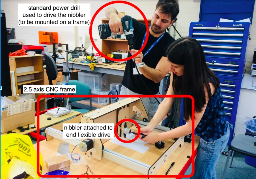
In our design, the nibbler is powered using a standard power drill which is mounted above the machine, and attached to the nibbler using an end flexible drive. The flexible drive allows the drill to be located away from the action, so it doesn’t take up working space.
The nibbler will move on the X and Y axis, using pulleys controlled by stepper motors. Where possible the parts have been laser cut and 3D printed and maybe one day, a metal version could be made using this machine, in a similar way to the RepRap 3D Printer. Here's an image showing the basic concept.

Here are the latest part files for download
Here's how the design has progressed this week:


General frame design and roller system on the gantry.
Boring out the pinion on a lathe (from 5.0 mm up to 6.35 mm which will be connected to the stepper motor).
Designing the pulleys to be press fit around the bearings.
Moving the gantry by hand to check alignment, friction, general stability.
Testing the pulley/belt drive to see that it all moves smoothly and that the teeth engage, without slipping or too much friction.
cutting aluminium using a drill which is directly connected to the cutter (no flexible shaft).
Using the mechanical setup to cut an 1mm aluminium sheet.
Follow-up test, we realised that there could be some issues with fastening the flexible drive to the nibbler. This test proved that issue, it's something we'll need to sort.
Conceptual demonstration of the machine.
Mechanical Design: Drive (gears, belts, pulleys) Frame Materials