Computer-controlled cutting
This week's assignment is to cut somthing on the vinylcutter and to Design, lasercut, and document a parametric press-fit construction kit, accounting for the lasercutter kerf, which can be assembled in multiple ways
- vinylcutting
- using silhouette cameo software
- vinyl experimenting
- Characterizing the lasercutter
- Test Part
- Press fit
- Downloadable files
- Extra design
vinylcutting
I decided to cut some shapes that I can use on my claw machine for my final project. I decided to cut the shapes that would go on the control pannel. Arrows to indicate directions for the joystick and the words "start" and "stop" to stick near the buttons that would do those functions. I also decided to experiment by cutting a shape from a retro game (super mario bros)
InkScape
I used inkscape editor to design the shapes i wanted to cut. Inkscape is a professional open source vector graphics editor that is used to create a varaity of graphics.

I used Inkscape's free drawing tool to create the shapes that I wanted.
Inkscape tutorial

silhouette cameo
The cutting machine I am using is a silhouette cameo. I've opted to using the silhouette cameo software which I downloaded through their website
Cameo software

I've exported the design from Inkscape in the form of a PNG image which I then opened in the Cameo software.
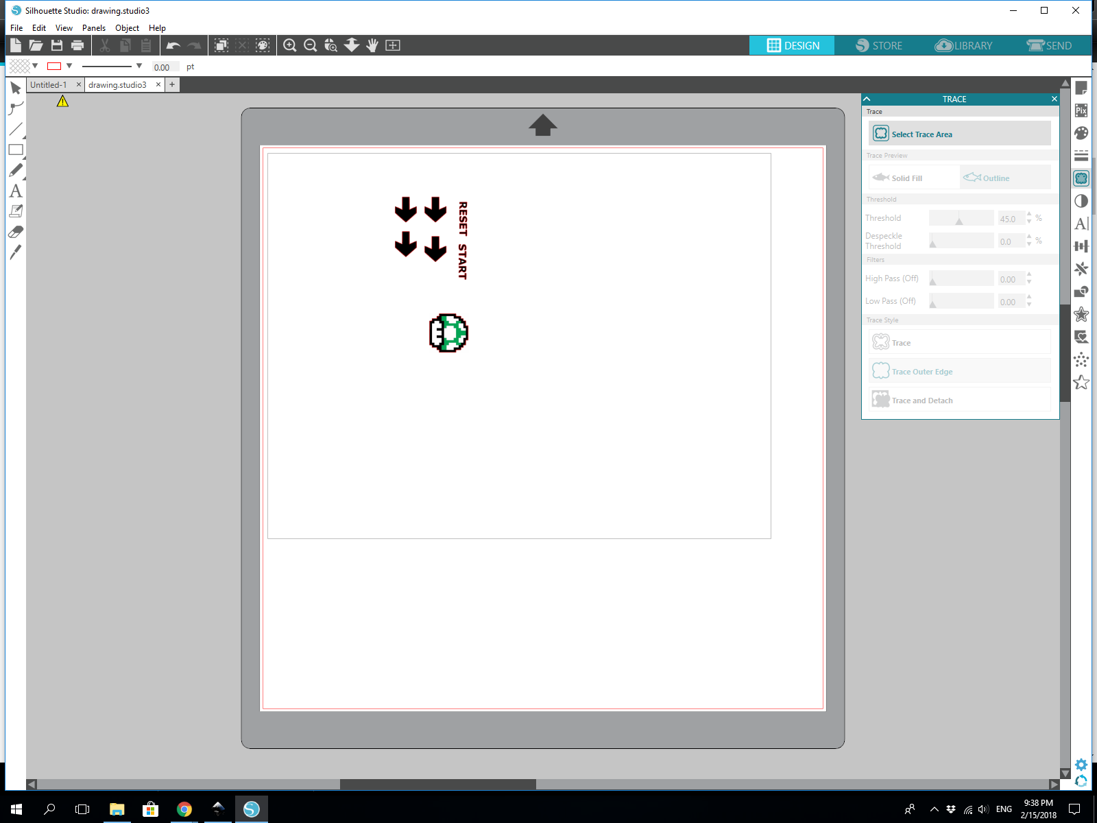
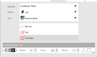
The software has a very helpful trace feature that automatically detencts the edges of an image to determine the cut area. After doing so I started experimenting with cutting settings. First I used random cutting settings to see the effect.
The result:
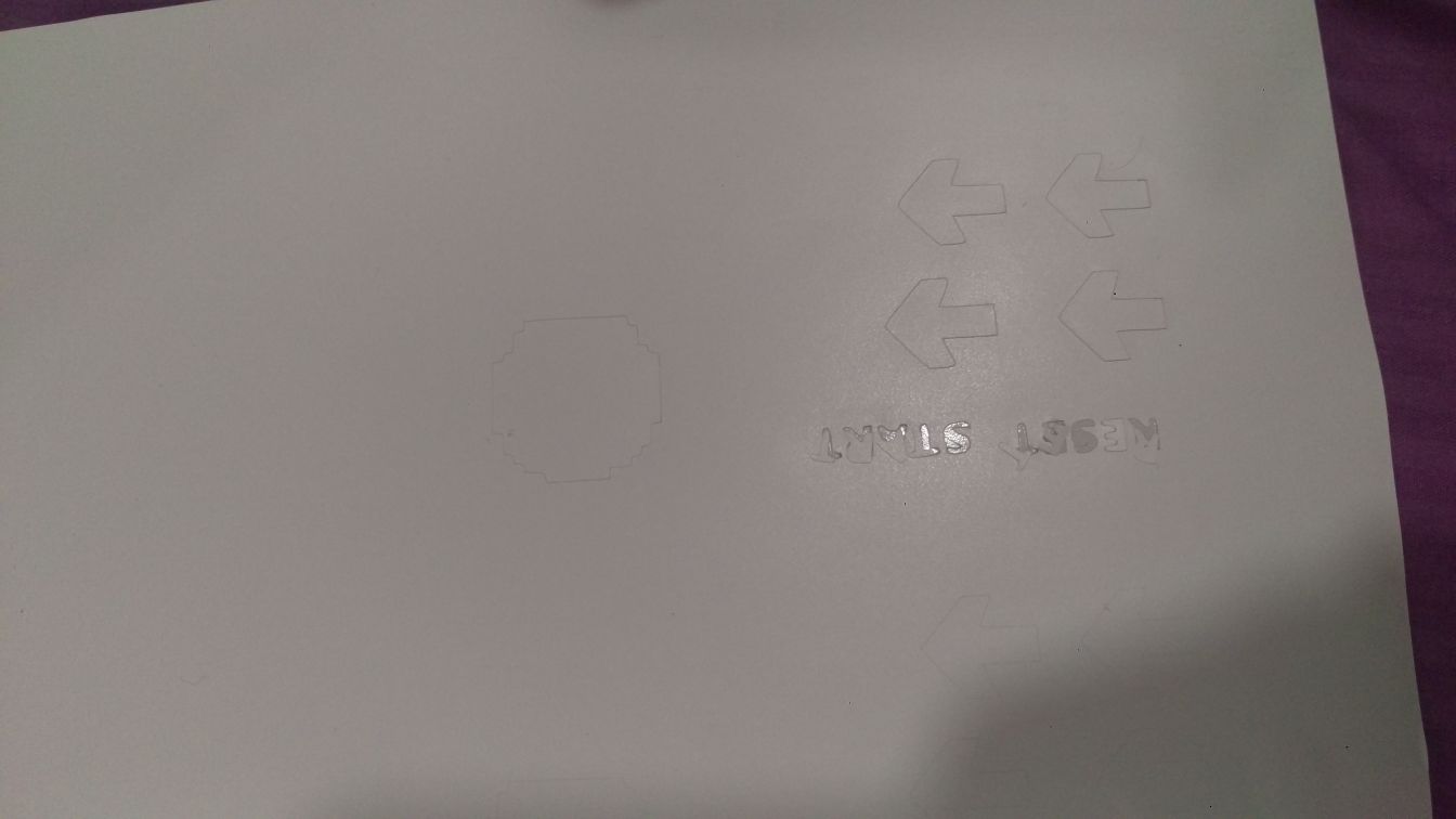
As the picture might(not very clearly, I tried)show, the letters of the words have been ripped out of place during the cutting process, which led me to believe the force used was too strong. It was set at 20.
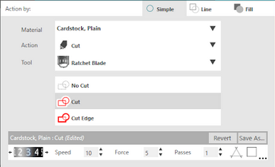
So I changed the settings to see the effect and tried again.
The result:
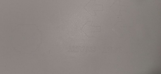
This attempt barely shows up in the picture (and in real life as well). the force was set to 5 in this case. It did not cut deep enough to be able to remove the shape at all.
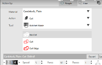
After the experimenting with various speeds and forces to see the effect, I've used the suggested default vinyal cutting settings in the software. (force =10).
The result:
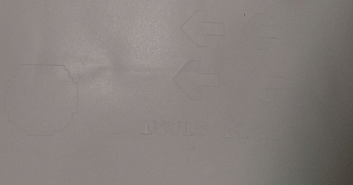
This time, it did cut it properly without ripping off the letters and the force managed to cut the vinyal deep enough.
Additional vinyl experimenting
This part is written ten weeks after completing the previeous part, I created my final project and need to decorate it. I decided to use vinyal cutting again.
I havent seen many people on fab academy using photoshop to design probably cause it isnt open source, but its a very fast tool to create a simple design (in my opnion).
My final project is an arcade playing retro black and white games. I wanted to recreate a simple loading icon and create it as a sticker. I used an 8 bit font to create the effect and the rest of the design was pretty much all rectangles! only took ten minutes.


Im using the cameo software again to cut on glossy vinyal material. i used the default settings.


transferred the sticker using a masking tape. the cuts were very small so some things didnt get transferred on the masking tape. after that i put the sticker on the arcade, pulled it carefully and removed the extras (like inside the A) using tweezers and put the dots back in using the tweezers as well.


Laser cutting
The assignment is to parametrically design and cut a design using a laser cutter and to characterise the lasercutter.
Testing the laser cutter
The laser cutter i am using is an Epilog laser mini

I am cutting cardboard that is 1.2mm thick. I just had to put it in and check that the zero point was within the cardboard

To test the laser cutter, i wanted to test as many elements at once to be able to see how the laser cutting process works and how the laser cutter handles different things like rastoring and cutting. i used This very helpful Laser cutting materiale template which includes a lot of the things I wanted to test at once.

The method used to send the design is quite simple. I am simply opening the design saved as dxf or svg and just going to the printing settings like i would in any normal print ( like printing on paper) and there i am selecting the laser cutter as my printer and changing the settings and then select print!


For setting the speed and power settings i used the epilog manual which suggests the appropriate speed and power for different cutting material. i used the matboard material settings.
I used color mapping to select what colors to cut and what colors to rastor. i picked red and blue becuase thats what i had in my design (i edited the test design in illustractor).

Then it was time to cut


you will notice that the rastering did not work. it did ingrave but it did it equally for all shades. I checked what was wrong in the settings.
I noticed that in the job preview it was detecting them all as one shade rather than multiple shades as it should

I tried changing multiple settings and checking the job preview, I changed the raster settings to 3D rastor and that seemed to fix it in the preievw.


I tried to redo that part alone a second time.

The lighter shades in the cardboard are the deeper ones. it worked right this time!
testing before designing the press fit
Before designing my press fit pieces, I wanted to test how they would fit and what size to make them, so i made a test part on solidworks with varying fit sizes to pick the right one. the cardboard is 1.2mm when i measured it with a vernier but that does not mean designing it on 1.2mm will be the perfect fit. the laser cutting is not perfect. i tried different sizes to select from them.

I adjusted the design colors in inkscape after saving it as a dxf from solidworks, and i added the measurments to be adble to tell which one works best when i try it after cutting.


The size that worked best when testing the design was 1.05 mm, sizes 1.1 mm up to 1.2 mm worked as well but were slightly loose.
The design
I made a design in tinkerCAD before realising that this was NOT in fact a parametric design. A parametric design wouldnt have seperate parts you change the sizes of manually (which is what i did), it has to change automatically.
So, I did not cut that design, and moved on to creating an actual parametric design.

I chose to use Solidworks to create my design. Solidworks is a great software for desiging and has lots of options to use when creating a parametric design.
Solidworks is a 3D design software but I am just creating a 2D design here.
To create the same design that I created in TinkerCad, first i just started with creating a circle and three simple lines in the sketch tools window.
Next is to use the trim tool to remove the tip by using the trim tool loacted in tools > sketch tools > trim

Next is to create the pattern all around the circle, I selected the three lines and and used the circular pattern tool located in tools > sketch tools > circular pattern.
This tool allows you to select how many times the shape would be repeated, the angles and the spacing between them.
With that I created a design with 8 trims around the circle, all equally spaced away from each other and all the same size. As per the test design results, I made the width 1.05mm to have it fit well. (downloadable file linked below)


Downloadable files
This section includes all the designes made during this week.
Vinyal cutter 8 bit loading design - photoshop file (.psd format)
Here
Vinyal cutter 8 bit loading design - image file (.png format)
Here
Laser cutter test design (.dxf format)
Here
Laser cutter parametric design (.dxf format)
Here
Extra parametric design
During my effort to learn designing using openscad, I experimented making a parametric design using OpenSCAD using a single variable. I did not laser cut it but I am including the code here.
//parameters
number = 1.05; //cutting material thickness
number2= number * 12; //double the length of the cut
length = number * 40; //t
he length of the big square
tran= length /2 ; //the transformation value (cuts will be in the middle of the big square
//The design
    difference() {
        square(length); //big square
        translate( [tran,0,0] ){
            square([number,number2], center = true);}
        translate( [tran,length,0] ){
            square([number,number2], center = true);}
        translate( [length,tran,0] ){
            square([number2,number], center = true);}
        translate( [0,tran,0] ){
            square([number2,number], center = true);}
        }
