Week 4 - Computer-Controlled Cutting
Week 4 was all about computer-controlled cutting i.e. CAD. Fab academy has a large collection of recomendations for tools such as Vinyl,laser, plasma, waterjet and hot wire cutters for students to get acquainted with. The full list can be found under 2018 class archive here.
Fabacademy students are expected to deliver a weekly assingment for this week on:
Group Assignment
I started this weekly assignment by looking into our laser cutter. As I am the only one taking the fabacademy in our lab, I am the group.

Laser Cutting Theory
Conventional light produces waves, which radiate out in all directions to fill up and illuminate a wide area. The energy intensity rapidly decreases as waves moves away from the source, just as the sun's intensity is diminished when it finally reaches the earth.
The laser on the other hand provides a stream of collimated, coherent light waves which give it exceptional intensity and direction ability. Lacking the dispersion of conventional light, a laser can be easily projected as a beam over relatively long distances while maintaining nearly all of its useful power output.
The use of lasers for cutting can be thought of in the same way as that of focusing sunlight with a magnifying glass to produce a concentrated source of heat energy. While this method only results in a few burned holes in paper, it gives us an illustration that light is indeed a source of energy with potential material processing capabilities.
A laser can be used for cutting by exposing material to the intense heat energy developed by its beam. If that heat input to the material is greater than that material's ability to reflect, conduct, or disperse the added energy, it will cause a sudden rise in temperature of the material at that point. If the temperature rise is substantial enough, the input heat is capable of initialising a hole by vaporizing the material. The linear movement of this intense heat energy with respect to the material provides cutting action.
Power Output
Lasers are rated by their power output in terms of watts. Since laser cutting is a thermal process, the amount of heat produced relates to its capabilities.
Our Epilog laser cutter is 60 watt laser. This output is more than adequate for the cutting paper products,MDF, Plexi glass upto 10mm in thickness. But it lacks the heat producing capabilities to effectively couple into aluminium. Other considerations being equal (eg power distribution, spot size, etc), increased power allows for faster processing speeds and the ability to cut thicker sections of materials.An important asset of laser cutting is the high level of control, which is available over the variables affecting the process. The cut can be tailored to meet the exact requirements of the job and the results can be readily duplicated. The principle parameters are:
Speed
Laser cutting feedrates have been found to fit empirical formulas based on the available laser power density and the properties of the material to be cut. Above a threshold amount, the feedrates are directly proportional to available power density, which takes into account the laser's performance features (eg power, mode) in addition to the focusing system's characteristics (eg spot size).
Focusing Lens
Since speed is a function of available power density, the choice of the focusing lens has a great impact on the resulting cut quality.Because the focused spot size is proportional to the focal length, the power density that is produced is proportional to the square of that length. Short focal length lenses give very high energy densities, but are limited in their application due to a shallow working depth. They are appropriate for use with thin materials and in high-speed operations where the material can be held within the limited depth of field. Longer focal length lenses have lower power densities but are able to maintain those densities over a much broader range and therefore can be used for thicker cross sections of materials given that they have enough energy initially.
Focal Point Position
During the laser cutting process, the focal point of the lens should be consistently positioned in order to provide the best cutting results. The Auto focus function on the reference section of the driver software is a much convinient option than manually focusing the machine every time we work with different thickness of materials. However, Manual focusing could be handy in case if we have non-Flate material.
Assist Gas
Air assist is supplied coaxial with the focused beam to protect the lens and aid in the material removal process.
Laser cutting systems combine the heat of the focused beam with assist gas, which is introduced through a nozzle coaxial to the focused beam. The high velocity gas jet serves to:
· Aid in material removal by blowing out excess material through the backside of the work piece
- Protect the lens from spatter ejected from the cut zone
- Assist in the burning process.
The delivery pressure of our compressor is about 45-60 psi (3-4 bar).This provides Compressed air coming from an air compressor atched to the air duct in the laser cutter is used to purge melted and evaporated material from the cut zone while minimising any excess burning. to prevent the clinging of slag or dross to the back edge of the cut.
LASER CUTTING PROCESS
While our carbon dioxide lasers is capable of generating tremendous heat intensity, it is an incorrect assumption that they are capable of vaporising and cutting all known materials.
Rather, each material has its own unique response, some of which are not
suitable, to the effects of CO2 laser. Therefore, the question of
suitability of using a laser for cutting that material hinges on how well
it handles the added energy input.
The following information is intended to
provide general inputs on the major categories of materials, keeping in
mind these is a parameter intended to be used with 60w Epilog
Over 150 settings for different matrials
The advantage of laser cutting is the simplicity of handling without having
to worry about stretching or distorting of the material due to the impact
of a cutting tool.
Fresh cut samples tend to exhibit slight stickiness
along the edge so they require care in post-process handling. Additionally,
some rubber, particularly those containing carbon black, may require a
clean-up operation to wipe clean any edge charring.
While the use of a laser likewise
eliminates rough, torn-out, and fuzzy edges as evident with conventional
sawing techniques, it is characterised by "burned" edges produced by the
laser's heat.
Make sure that the lense is cleaned. Specially after ingraving rubber. You also have to keep an eye on the cabon dioxide tube as it is one of the consumable parts of the machine. With our rate of use in Aalto fablab, We need to replace the tube in appro. 3.5 years.
Laser Cutter Assignment
To determine the power and speed settings for 2mm stiff cardboard and 3mm corrugated cardboardI used Epilog's recommended settings as a starting point, I drew a number of 20mm x 20mm squares and tried different combinations of speed and power in order to determine the optimal settings for the cardboard material that I will be using.

The same 20mm x 20mm squares can be used to determine the kerf for our
Epilog laser. I measured the values of the outside edges of the square and
the inner edges of the resulting hole. The difference in the 2 values,
divided by 2, gives the kerf for each material. Using this technique, the
kerfs for the 2 complete cuts were as follows:
| Laser Setting | Square (inside) | Hole (outside) |
|---|---|---|
| 10/50/50 | 19.84, 19.76 | 20.02, 20.14 |
| 15/50/50 | 19.86, 19.86 | 20.09, 20.02 |
From the values above, the worse case kerf can be calculated:
- 2mm cardboard (SPD/POW/FREQ 10/50/50): (20.14mm - 19.76mm)/2 = 0.19mm
- 2mm cardboard (SPD/POW/FREQ 15/50/50): (20.09mm - 19.86mm)/2 = 0.12mm

One conclusion that can be drawn from the kerf measurements is that lower speed/higher power settings results in a larger kerf. This makes sense, as the laser, under those conditions, would burn away more of the base material. I drew the 20mm x 20mm squares in CorelDraw instead of Inkscape, for the simple reason that our Epilog laser is patched to a notebook with CorelDraw and shows up as a printer in CorelDraw. A screencapture of my CorelDraw test drawing is included and the file can be downloaded from here . The text was added to the drawing later.

Once the kerf is known, it is time to get started and make something useful.
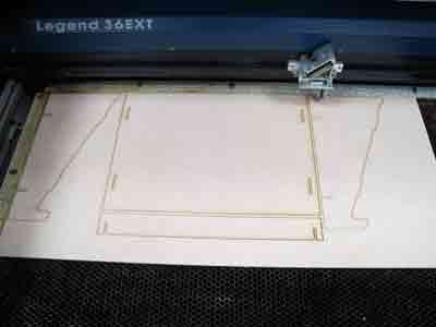
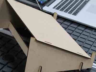
Combining last weeks new skill,I designed a laptop holder using Fusion 360. I defined parameters both for the kerf and the thickness of the material to be able to make it a fully parametric design.
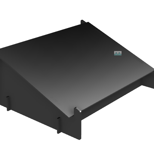
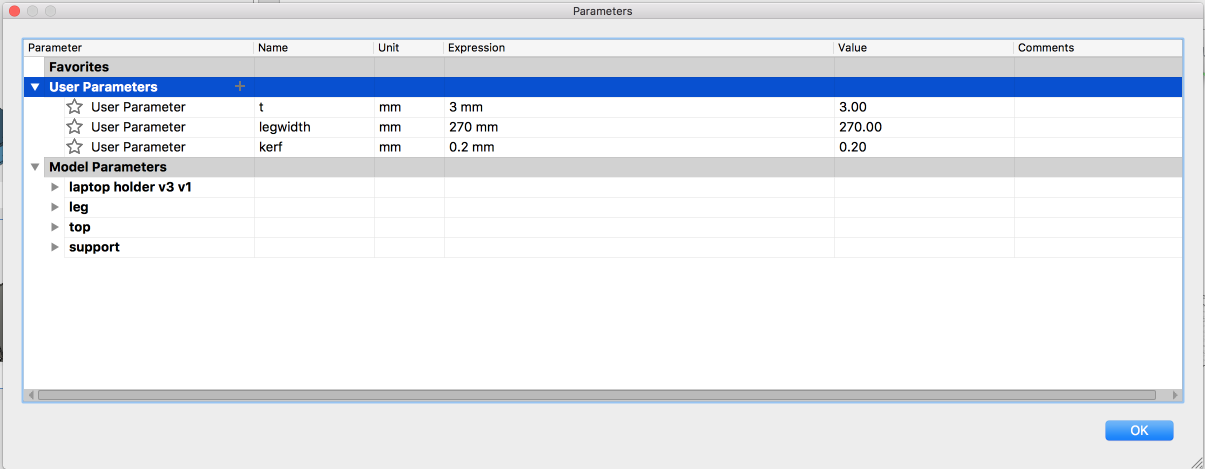
One issue that I had was how to move from my CAD model to Dxf file for our laser cutter. I found an open source DXF generator plug-in from the Autodesk App store to export the dxf format required. This is great help but one has to be careful not to put any kerf value if the kerf has already be included in the design.

Download
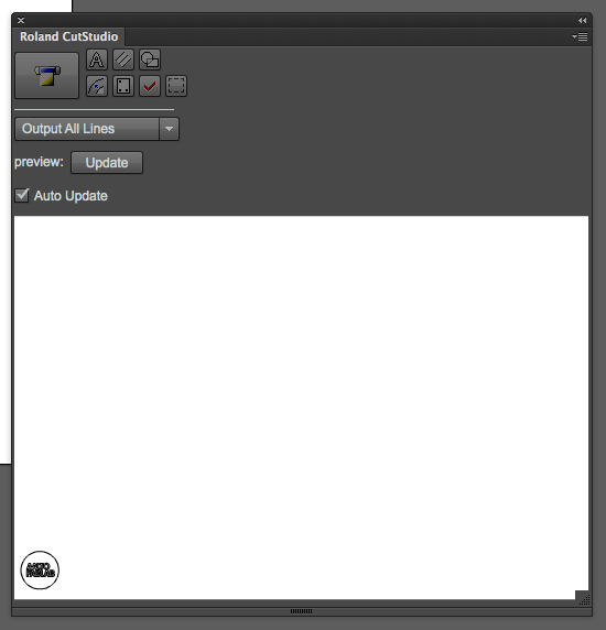
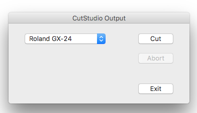
Vinyl Cutter Assignment
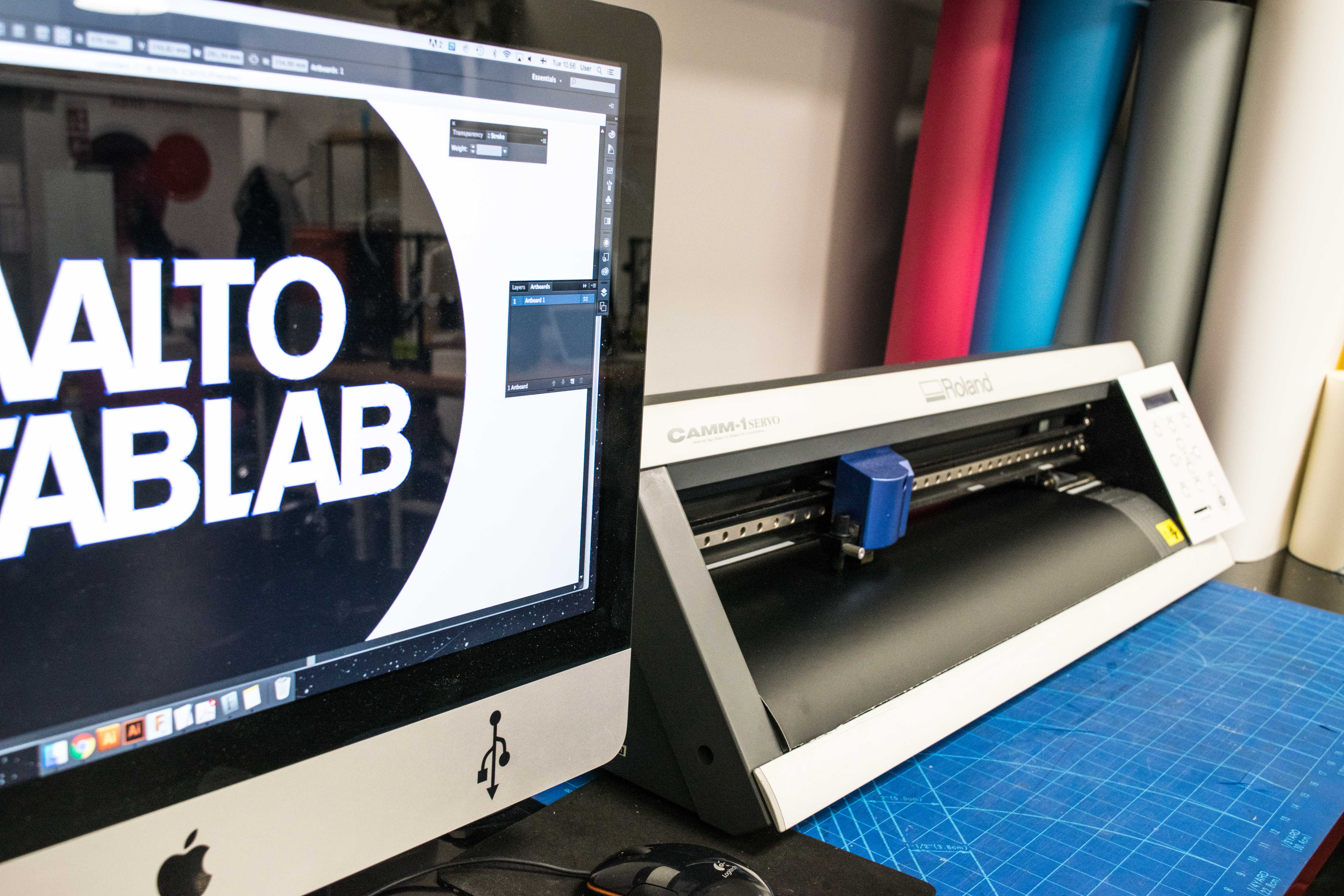
I wanted to make some Stickers with Aalto fablabs logo . I loaded my file in Illustrator adjust the artboard to match the size of the vinyl I have in the machine