lasercutter (group assignment)
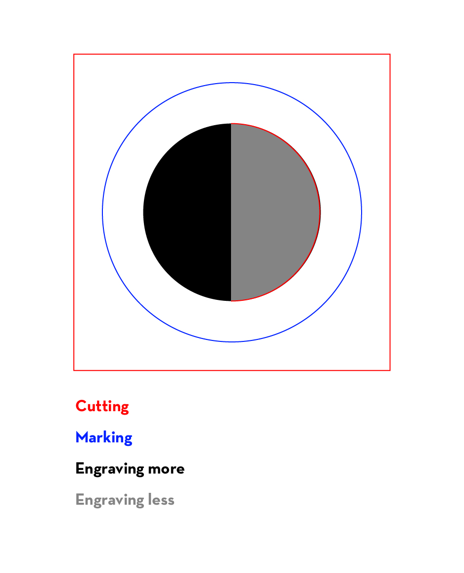
We got introduced to both the vinyl and laser cutter machines. It was great to see the endless things that these machines allow you to do. Here's a good presentation with examples of uses and outcomes with these machines. There are to basic output types that can be done with the laser cutter: vector(it will cut or mark through the vector line) and raster (treats image as a bitmap, burns material with different intensities).
Right after the induction we went ahead and tested the last one as a group (Dorota, Kris, Joris and me). I found this exercise very useful as it allowed us to collectively figure out the (maybe intimidating) process of cutting by laser for the first time.
There is a great standard test file, but we decided to create our own test-desgin as we didn't have much time and we wanted to test some specific things.
The design to be printed has to be in vector format such as .dfx or .ai but not .svg as Rhino cannot open it, and we will be using Rhino to send the file to the machine, this is how they communicate. (Remember to send designs to cut through the IAC server, as using a USB stick could involve viruses.
- Once the file is open on Rhino we execute the print command and select the machine to use (Trotec Engraver).
- Output type: vector for vectors, raster for bitmaps (slower), if a file contains raster and vector, choose vector.
- Scale: should be 1:1; set the working area to window (allows to move the working area relative to the design in Rhino
-Trotec Job Control opens. Press USB icon to connect to the lasercutter. Play icon appears.
- Drag and drop the job from the right side panel. Double click the area to check if it is your job. Remember to define the dimensions of the material area in Rhino print properties.
- In TJC you can snap the job canvas to the origin that we set on the machine.
- Go to Settings:Material Setup to set up material and colors. Do not check the Auto checkbox. Do not go more than 1.0 for the Speed value for any of the colors..)
- The variables we can play with are power, speed and frequency. We should test and reference the engraving speed. The rule of thumb is to start slow and go up from there. This step is really a trial and error process as there are not appropriate settings for each material, it depends on the finish and result you are looking for, although there are many standard settings forms that could be helpful to get started setting the values for each material.
- We place the material in the machine and manually adjust the height until the small plastic thingy falls down.
- Manually place the laser in the starting point and send job. (Right-click on design to do a Job Reset)
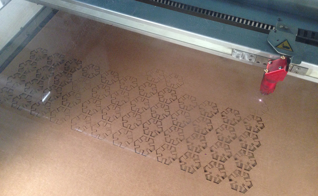
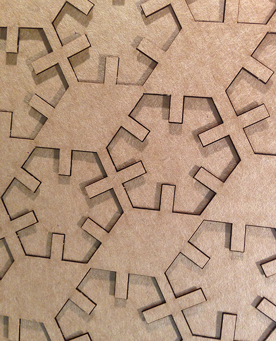
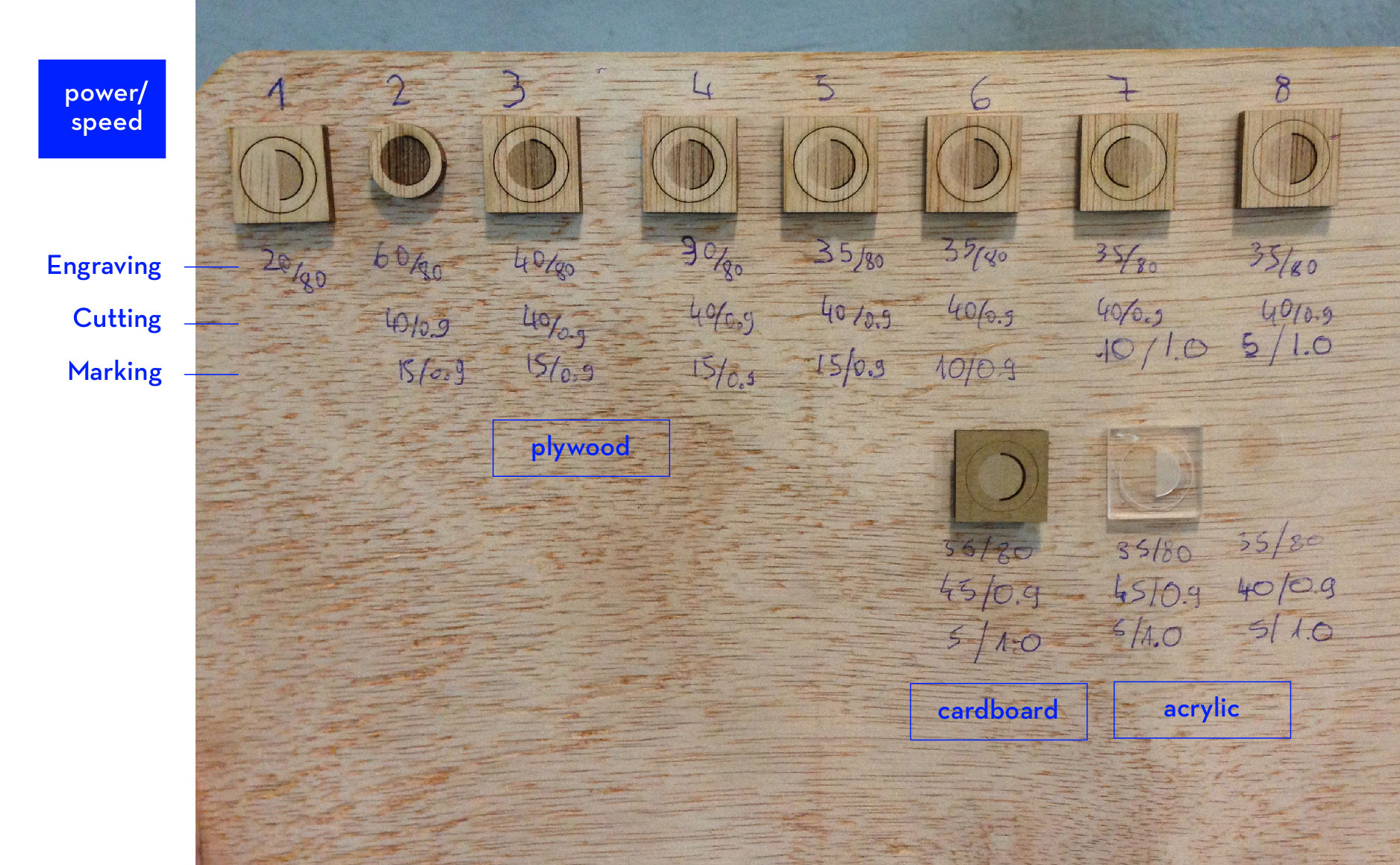 We decided to run our first tests on wood. As it can be seen in the image below, it took us a while to set the desired parameters. Once we were happy with the finish we cut the same design in other materials like plastic, and acrylic.
Fusion 360
In order to build a press-fit structure I need a parametric 3D software. I chose Fusion 360. Baptiste knew Fusion and he was kind enough to give me a great one-on-one amazing tutorial. Here basic things that I learned:
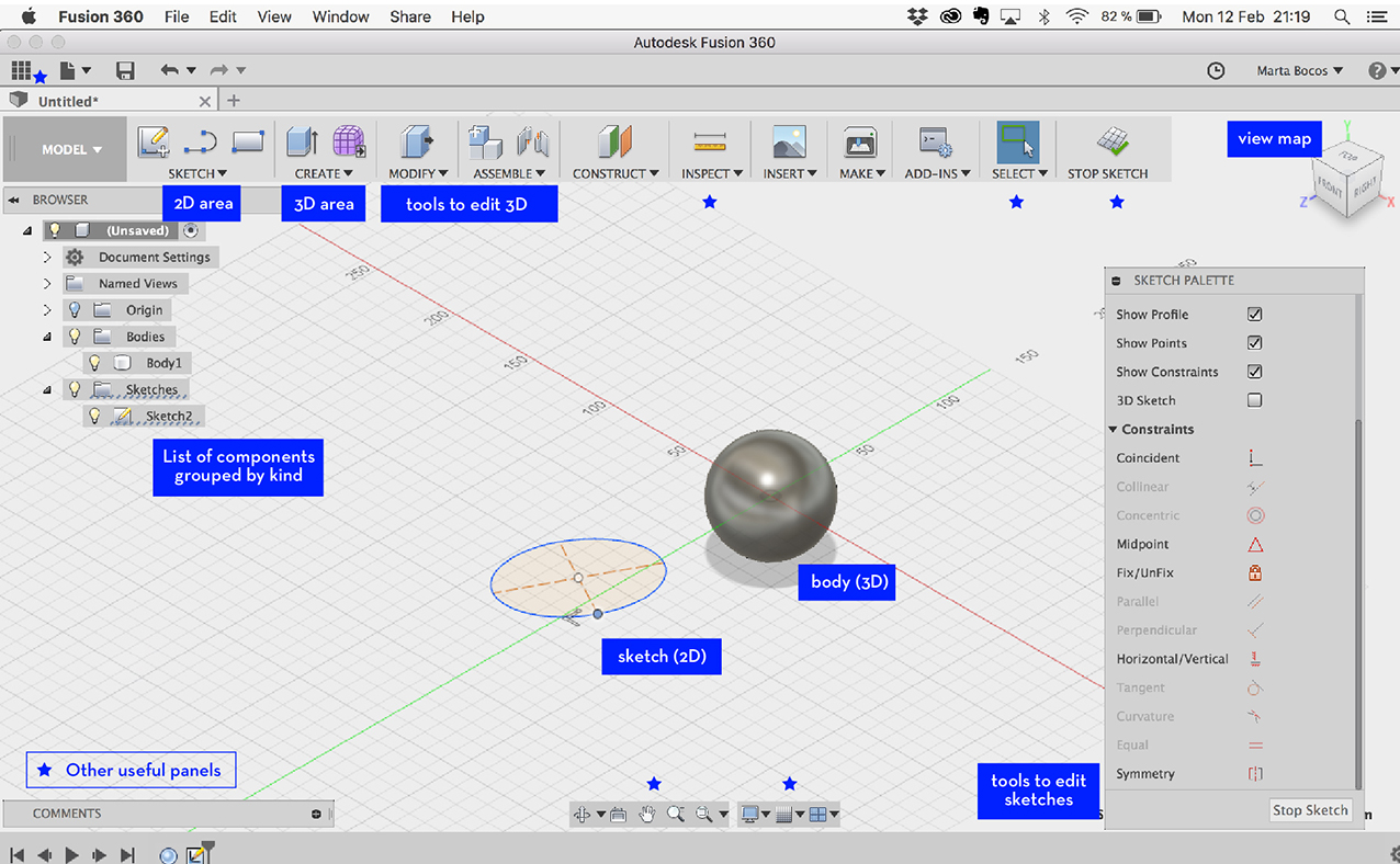
In the image above, the basics of Fusion workspace
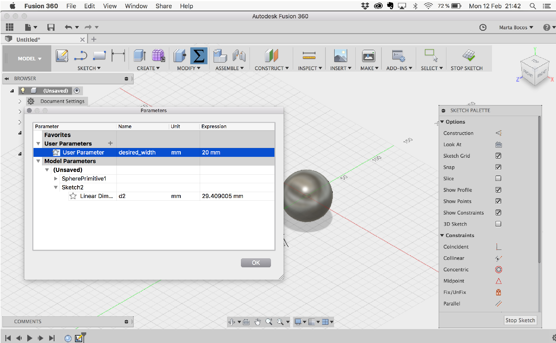
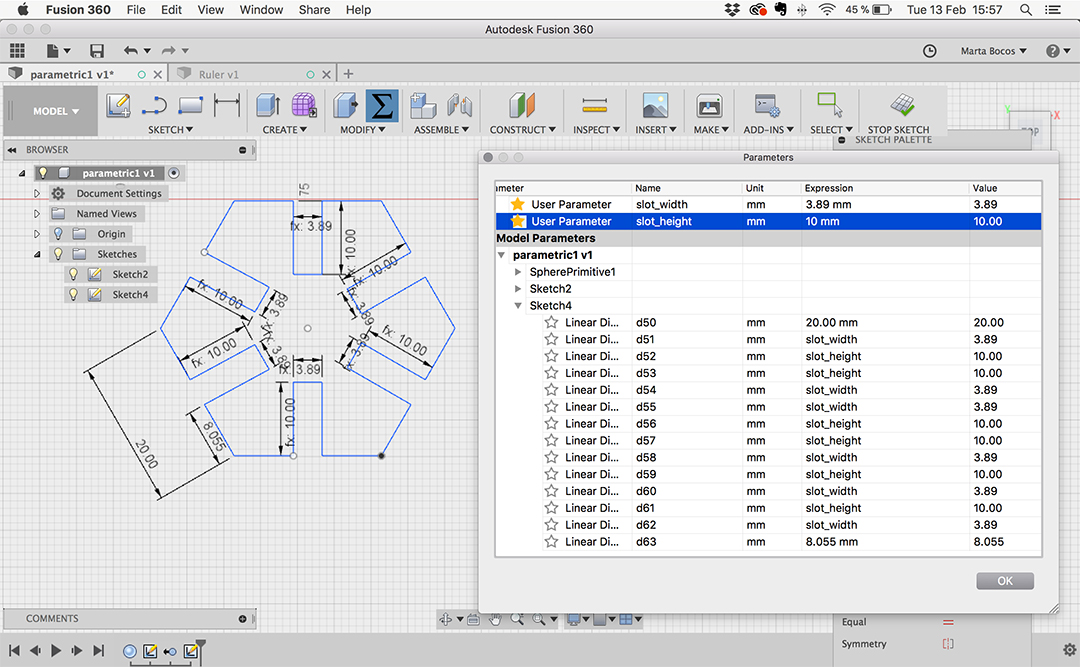
Important thing in Fusion is the Change Parameters option. Allows to assign x values to key measurements, so that when we change or modify the value of x all the values assigned with it will change as well.
Basic steps for working with Fusion:
- Roughly sketch your design
- Perfect with the sketch tools
- Set the dimensions for each part
- In case you want to turn it into an object (extrude...etc and continue design)
- To get ready for the laser cutter, save file with .3dm extension and open it in Rhino.
- Once in Rhino assign colors for each finish and save file in .dfx format.
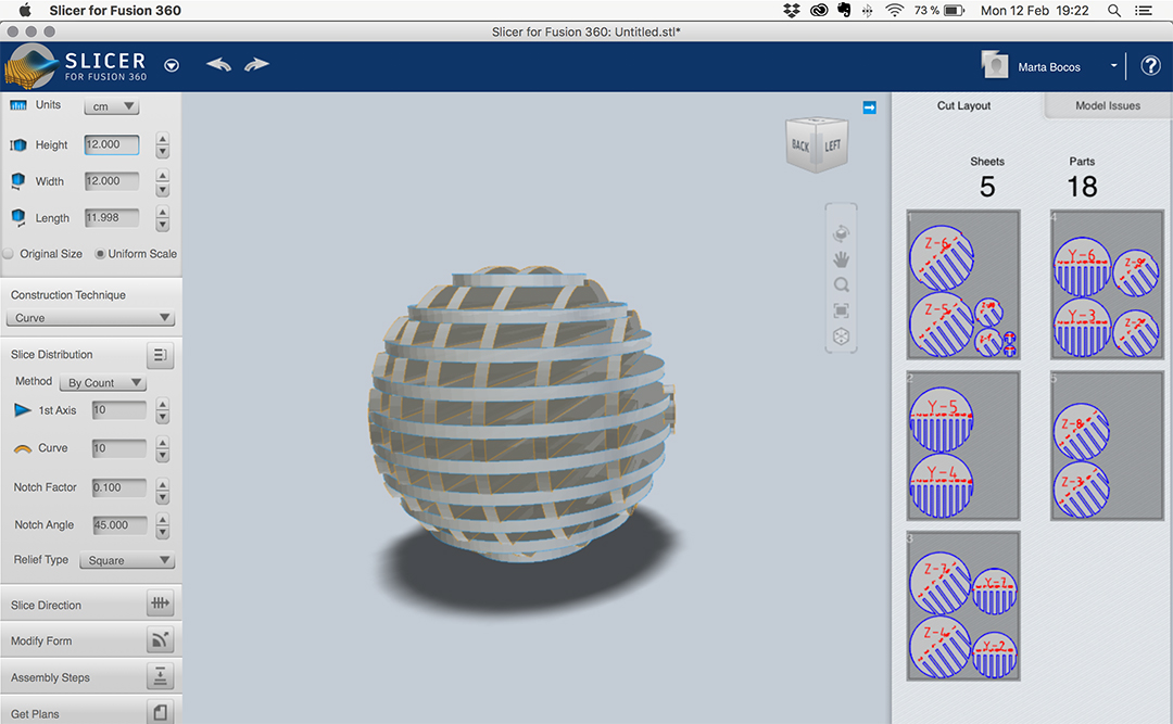
I am also curious to use Slicer to build a press-fit construction. Slicer is an add-on to Fusion that helps you work out the slices for a 3D object. I downloaded it and played around a little. Hope I have enough time to make something with it.
Press-Fit
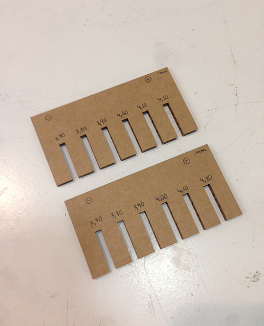
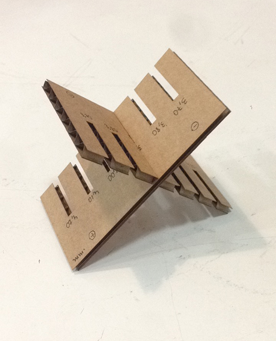
I started my pressfit construction by designing and cutting a ruler to test the slots dimensions and fittings. It was the perfect way to incorporate what I learned in Fusion and give it a practical use, also, by doing the whole process from design to production all together at once was easier to understand.
I made two small pieces with gaps that ranged from 3.70mm to 4.20mm (the cardboard was 4mm thick), so that I could test the best fitting when interlocking two pieces. After testing it I realized the best fitting was 3.90mm although maybe 3.89 could work too, adjusting the fit tighter.
After knowing the slot dimensions I proceeded to design a simple piece. I made an effort to apply most of the things learned in fusion, such as parameters for the dimensions of the slots.
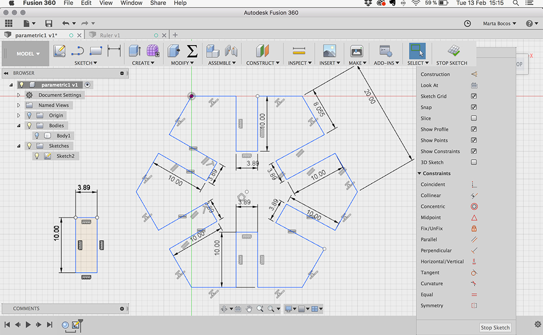
I applied two parameters to the slots: slot_height and slot_width, by doing so I'll be able to quickly change the slot dimensions afterwards.
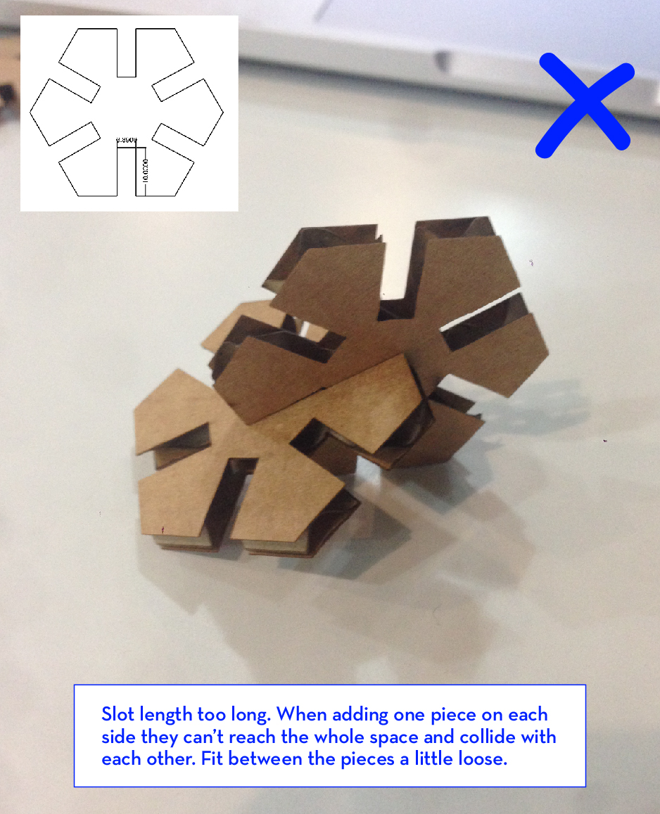
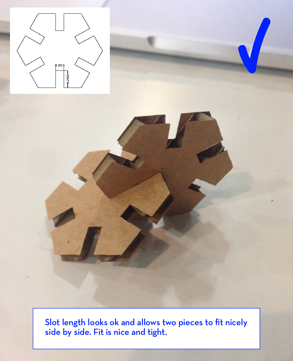
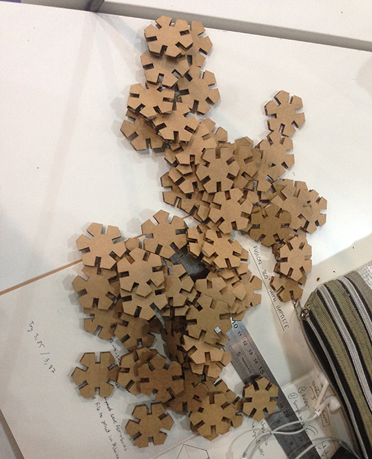
This time I decided to make two variations of the same piece so that I could test them before cutting the rest of the pieces. Learned from what worked and what didn't (explained on the images below) and proceeded to print copies of the version of the design which passed the test.
After the two pieces test I proceeded to cut more than 60 pieces of the designed that worked. I used the same parameters for speed and power that worked for me when testing the material in the group assignment, although I lowered the power a little because I didn't want such burned edges. When setting the cutting area in the laser-cutter always make sure scale is set to 1:1
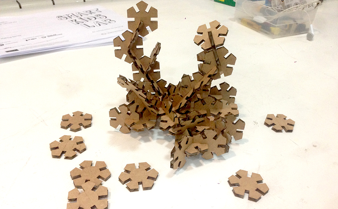
The result of the assembled pieces in the picture below. I take this is an starting point, now I want to improve from what I have. There are many things that I would do differently now that I have the piece in my hands, such as:
- Making the slot shorter. When I added more than 3 pieces together, they collided a little between each other and the structure wasn't stable enough.
- I would try out new shapes and probably make them bigger.
- I hope I can find some time to create a more complex design.
Test more, more and more before producing.
Be careful with duplicates of the shape on top for each other!
Files:
ruler (.dfx)
ruler (.3dm)
Press-fit (.dfx)
Press-fit (.3dm)
vinylcutter
I worked with a machine similar to the vinyl cutter a while ago, it was called Cameo and it was basically a small, domestic-version of the vinyl cutter we have in the Lab. I have also spent uncountable hours cutting artworks from paper with a sharp scalpel, this is why getting used to the vinyl cutter will be a definite improvement in my workflow.
I wanted to get out of my control zone, so instead of cutting a sticker or logo on vinyl I have decided to cut on paper and create an image using the shades and possible color cards in the background to add color. This is the image that inspired me.
But first, I wanted to test the machine, as after all, I am using it for the first time.
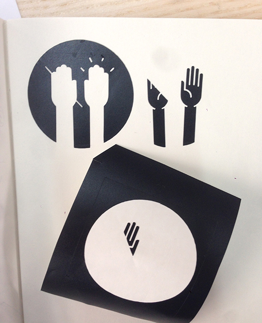
I designed a simple logo for a friend a while ago which I thought would serve well as a test. I started of with an image from thenounproject.com, using that as a guide, I drew my design on top with the pen tool in Illustrator.
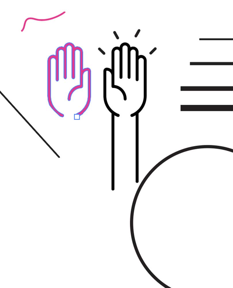
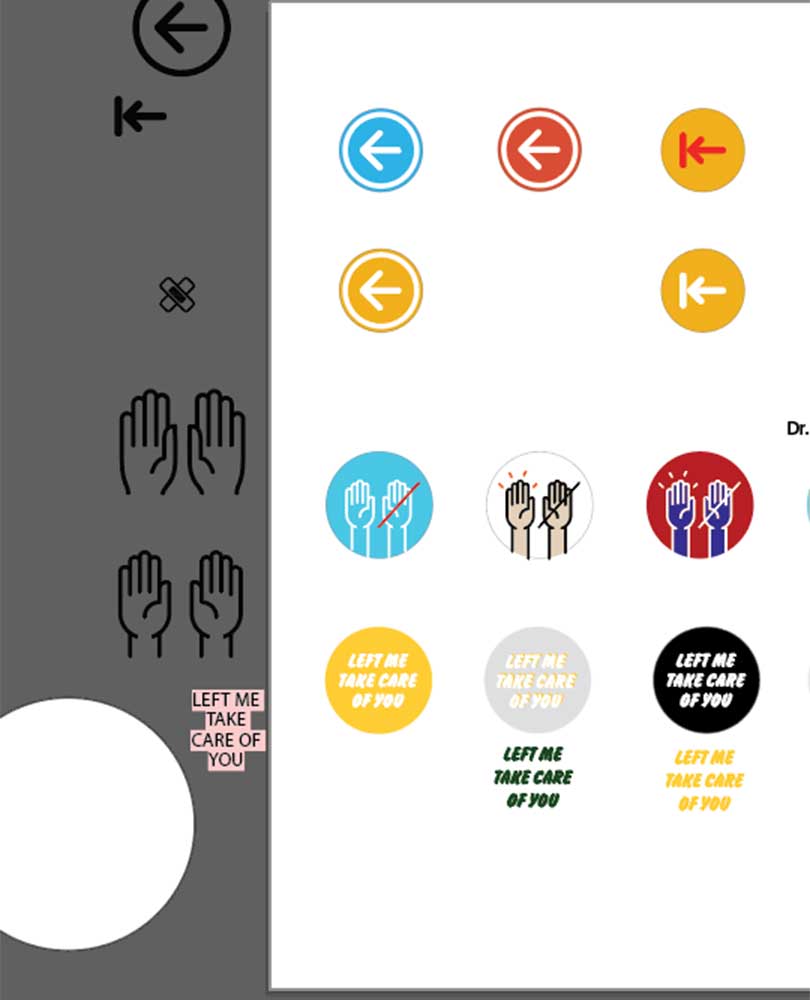
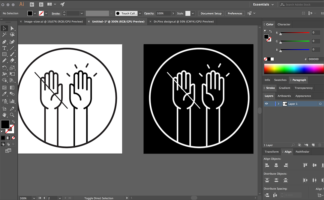
The mainly used the pen tool for creating the hand shape, and then spent some additional time moving the anchor points to adjust the vectors as I wanted them to look. After that, I proceeded to add the other elements like the arms, and exclamation marks, to draw that I used the simple line tool. I also played around on the screen with different stroke weights and settings to see other looks. (see images above). Once the two shands where placed inside the circle, I made the positive and negative of it painting with black and white or white and black. After that I exported it as an .svg and my test-image was ready.
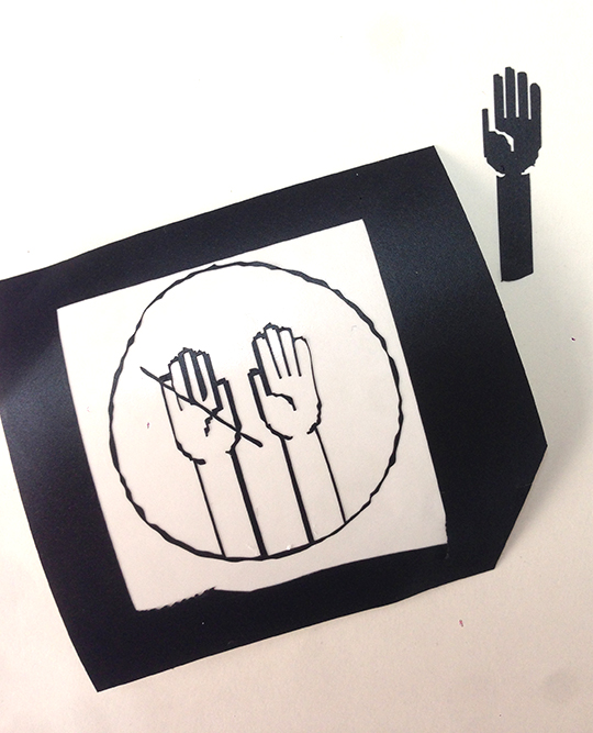
Here are my first two tests, which ended up in fails.
The first trial, the one with the wavy edges, was due to a conflict between the software languages. I learned that when you exported the .svg file into InCut (software for communicating to the vinyl machine) it makes the edges wavy for some unknown reason. The way to solve this is to scale the design up in Insksape and then paste it back on InCut and scale it down to the desired dimensions again.
The second mistake was choosing such as simple thing design with isolated pieces. I should have made a design that behaved like an interconnected block, like a stencil, otherwise, when the vinyl is taken out there is no way to place the inner parts in the right spot.
Now that I know how to properly cut with the vinyl cutter, I want to go ahead and do my mini-project.
Files:
vynil cutter(.ai)
vynil cutter(.svg)