measure something: add a sensor to a microcontroller board that you have designed and read it
My goal for this week is to integrate a motion sensor in the board I will create.
My long-term goal is to fabricate a simple device that when it detects movement around it will trigger a water spray. The reason why I want to achieve this is because I have a very naughty cat that scratches the sofa when I'm away, so I want to create this "cat trap" to prevent my evil pet to destroy the house.
I used Neil's Motion Board which looks like this as a guide and example for creating mine.
The motion sensor I will be using is called PIR Sensor v1.0 by Seedstudio, but I haven't found the exact datasheet for this one.
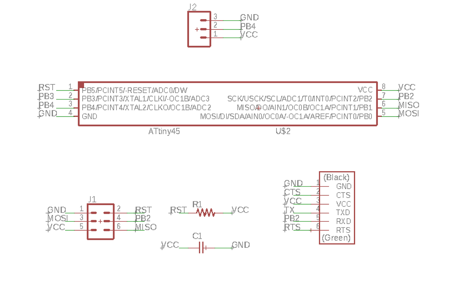
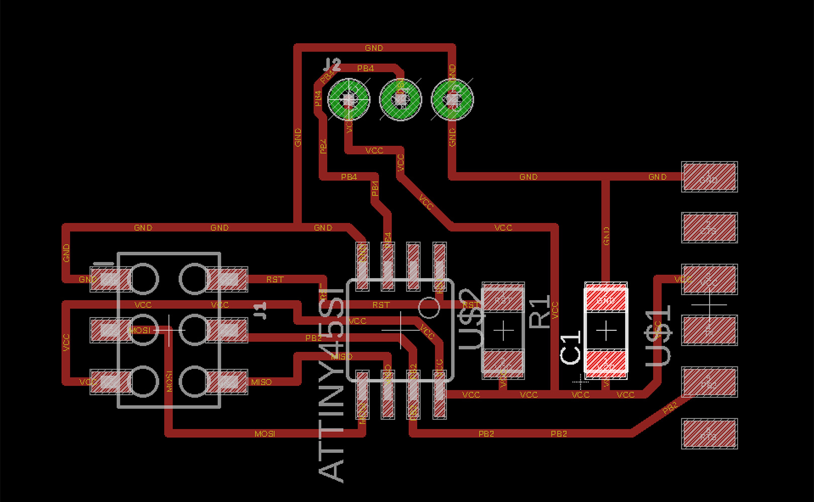
I designed the board on Eagle, the final result can be seen in the images below. Something that needs to be mentioned is that I had to look for a way to connect the sensor to the board, and because there wasn't any PIN that matched the sensor in the FAB library I had to look for one that would do the job. I downloaded this great library from Sparkfun that had the pin I needed. After that I just had to connect the components of my circuit as if the connector was the sensor.
In this board I learned something new, which is adding holes. Because of the nature of the sensor, it needs to be solded from the back of the board, so in order to do that I had to mill some holes into it. In order to do that, we will have to produce three .png and after .rml files instead of two as I've been doing until now. Eagle already recognizes that the component needs holes, so it marks them with a green circle on Eagle. When the board is ready we have to first export the traces image (traces white and background black), after that we export the items on the board that will be cut through: on the second place will export the pads (black inside part of the holes agains white bkg), and as the third and last step we'll export the cutout shape (black line against a white bkg).
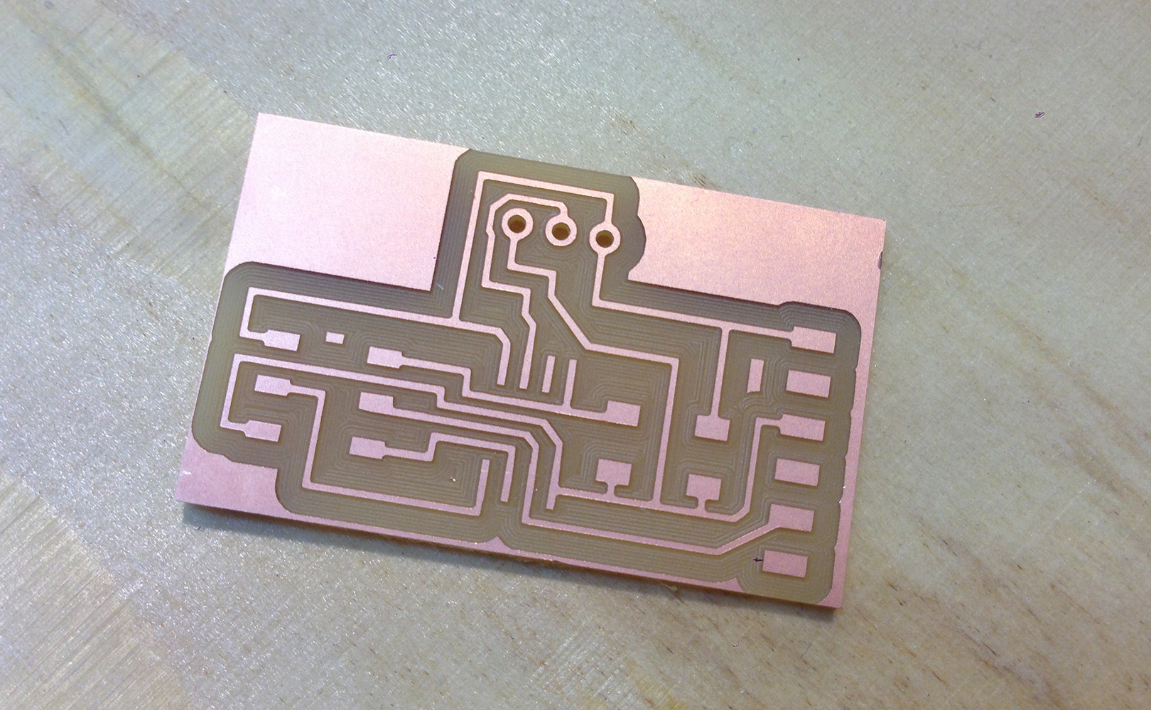
After all files are ready, in the milling machine the steps are the same: 1st.milling traces, 2nd.drilling holes, 3rd.cutout silouette.
The result of the board after being milled and drilled the holes and silouette below.
Final result of the board after having solded all the components below.
I made a small mistake which was relying
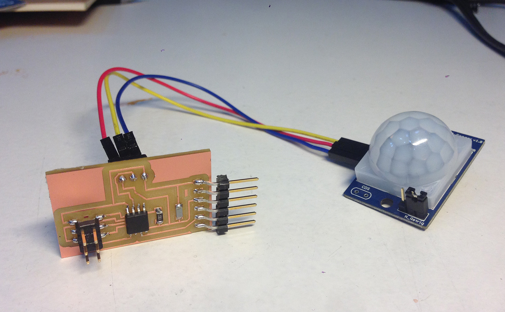
Small mistake:I relied too much on Neil's board, and I didn't pay atention to my sensor datasheet, so the outout pins were different in my sensor.
Solution:I solved this by adding three jumper cables to connect the sensor pins with my board. In the end it was a happy acccident because the cables add movement flexibility to the sensor and I think can benefit from it when I make the final structure.
Files:
Motion Board shematics (.sch)
Motion Board board (.brd)
Motion Board traces (.png)
Motion board holes (.png)
Motion Board cutout (.png)
Motion Board traces (.rml)
Motion Board holes (.rml)
Motion Board cutout (.rml)