INPUT
In this assignment I had to add an output device to a microcontroller board I've designed and program it to do something.
LESSON >> video recording - web

In this assignment I had to add an output device to a microcontroller board I've designed and program it to do something.
LESSON >> video recording - web
>>> MANUFACTURING
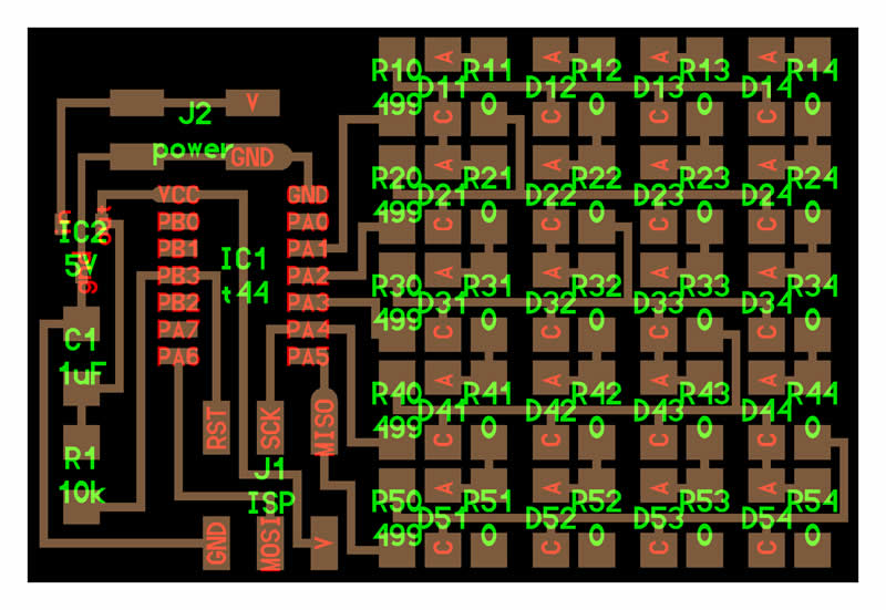
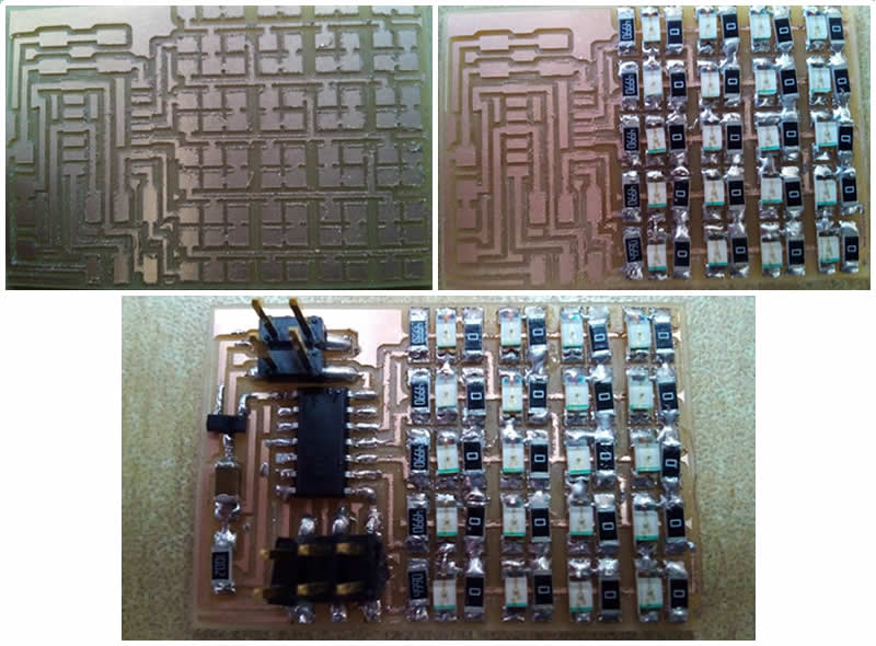
I wished to make the hello led array circuit and I used the knowledge of my assignment 04: Electronic Production.
Here the board:
Programming
I used the knowledge acquired in my assigment 07: Embedded Programming.
But I had some connections errors so I decided to created a new circuit.
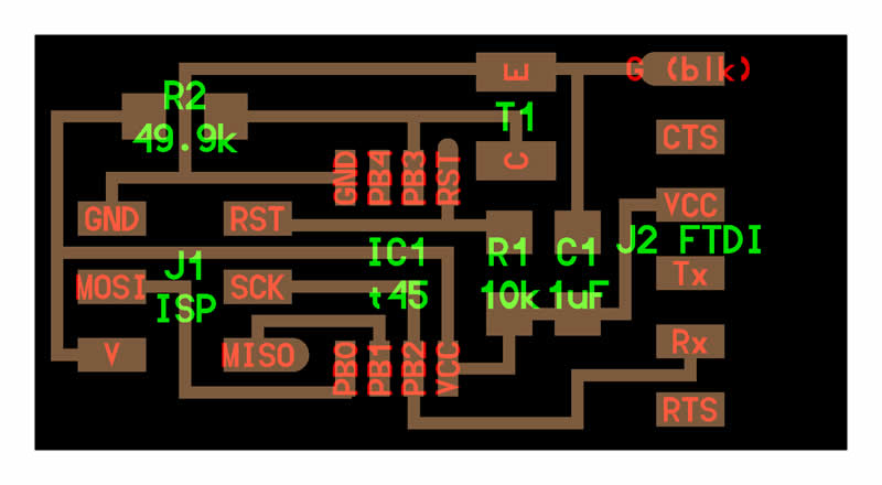
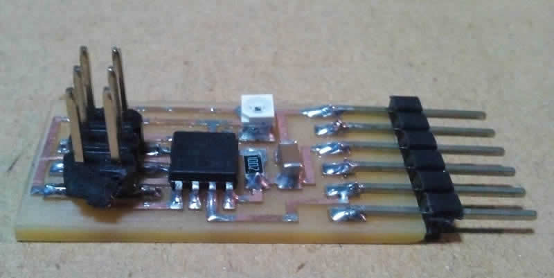
So finally I made the RGB Led Circuit.
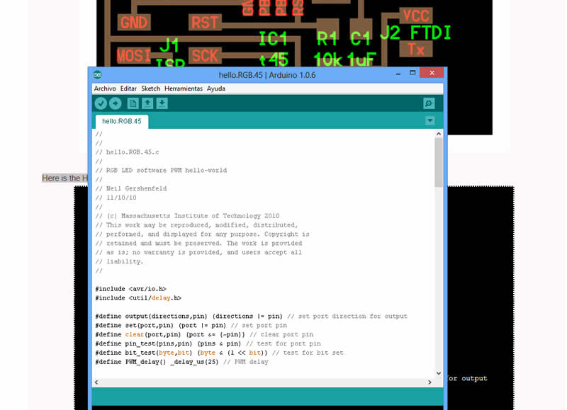
Here is the Hello RGB program
            //
            //
            // hello.RGB.45.c
            //
            // RGB LED software PWM hello-world
            //
            // Neil Gershenfeld
            // 11/10/10
            //
            // (c) Massachusetts Institute of Technology 2010
            // This work may be reproduced, modified, distributed,
            // performed, and displayed for any purpose. Copyright is
            // retained and must be preserved. The work is provided
            // as is; no warranty is provided, and users accept all
            // liability.
            //

            #include
            #include

            #define output(directions,pin) (directions |= pin) // set port direction for output
            #define set(port,pin) (port |= pin) // set port pin
            #define clear(port,pin) (port &= (~pin)) // clear port pin
            #define pin_test(pins,pin) (pins & pin) // test for port pin
            #define bit_test(byte,bit) (byte & (1 << bit)) // test for bit set
            #define PWM_delay() _delay_us(25) // PWM delay

            #define led_port PORTB
            #define led_direction DDRB
            #define red (1 << PB1)
            #define green (1 << PB0)
            #define blue (1 << PB2)

            int main(void) {
               //
               // main
               //
               unsigned char count, pwm;
               //
               // set clock divider to /1
               //
               CLKPR = (1 << CLKPCE);
               CLKPR = (0 << CLKPS3) | (0 << CLKPS2) | (0 << CLKPS1) | (0 << CLKPS0);
               //
               // initialize LED pins
               //
               set(led_port, red);
               output(led_direction, red);
               set(led_port, green);
               output(led_direction, green);
               set(led_port, blue);
               output(led_direction, blue);
               //
               // main loop
               //
               while (1) {
                  //
                  // off -> red
                  //
                  for (count = 0; count < 255; ++count) {
                     clear(led_port,red);
                     for (pwm = count; pwm < 255; ++pwm)
                        PWM_delay();
                     set(led_port,red);
                     for (pwm = 0; pwm < count; ++pwm)
                        PWM_delay();
                     }
                  //
                  // red -> green
                  //
                  for (count = 0; count < 255; ++count) {
                     set(led_port,red);
                     clear(led_port,green);
                     for (pwm = count; pwm < 255; ++pwm)
                        PWM_delay();
                     clear(led_port,red);
                     set(led_port,green);
                     for (pwm = 0; pwm < count; ++pwm)
                        PWM_delay();
                     }
                  //
                  // green -> blue
                  //
                  for (count = 0; count < 255; ++count) {
                     set(led_port,green);
                     clear(led_port,blue);
                     for (pwm = count; pwm < 255; ++pwm)
                        PWM_delay();
                     clear(led_port,green);
                     set(led_port,blue);
                     for (pwm = 0; pwm < count; ++pwm)
                        PWM_delay();
                     }
                  //
                  // blue -> on
                  //
                  for (count = 0; count < 255; ++count) {
                     set(led_port,blue);
                     clear(led_port,green);
                     clear(led_port,red);
                     for (pwm = count; pwm < 255; ++pwm)
                        PWM_delay();
                     set(led_port,blue);
                     set(led_port,green);
                     set(led_port,red);
                     for (pwm = 0; pwm < count; ++pwm)
                        PWM_delay();
                     }

                  //
                  // on -> off
                  //
                  for (count = 0; count < 255; ++count) {
                     set(led_port,blue);
                     set(led_port,green);
                     set(led_port,red);
                     for (pwm = count; pwm < 255; ++pwm)
                        PWM_delay();
                     clear(led_port,blue);
                     clear(led_port,green);
                     clear(led_port,red);
                     for (pwm = 0; pwm < count; ++pwm)
                        PWM_delay();
                     }
                  }
               }
 How it works?
Fading: Demonstrates the use of analog output (Pulse Width Modulation (PWM)) to fade an LED. PWM is a technique for getting an analog-like behavior from a digital output by switching it off and on very fast.
How it works?
Fading: Demonstrates the use of analog output (Pulse Width Modulation (PWM)) to fade an LED. PWM is a technique for getting an analog-like behavior from a digital output by switching it off and on very fast.
>>> VIEWING
After load the code using arduino software this was the final result: