Computer-Controlled Machining
Assignment- Make Something Big
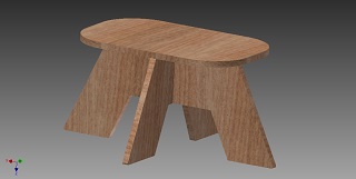
This week assignment we are task to make something big. It is back to drawing block and i have to reckon my brain again to think what to build for this week assignment. A few idea pop up like a shoe rack , chair and a stool. As i am not a mechanical trained so i decided to make some easy which i can easily manage during the cutting using the router machine. For this assignment i be again using Autodesk Inventor to design my stool. In addition, i have also go through some tutorial to learn how to use master cam software before i am ready to use the router machine.
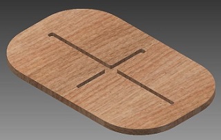
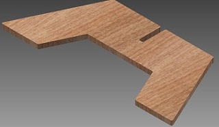
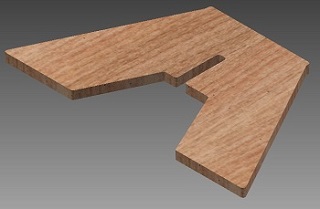
Images of Design parts
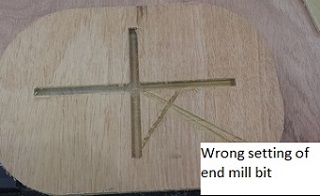
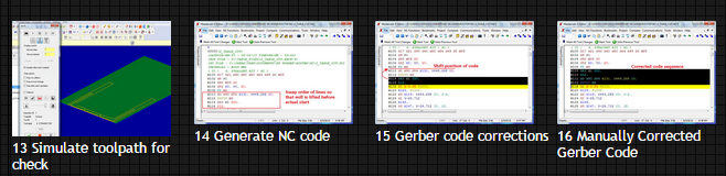
My first trial was failure as shown in the picture. It is my first time converting the files to .NC on MasterCam
The seond trial was success as shown in the picture after a check on the coding and the bit end point.
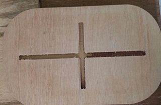
With the sucession of the second cutting i am more determined to finished up my CAD work and ready to convert the files on MasterCAM.
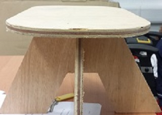
Images of Actual parts
You can find my CAD files here:
Leg 1, Leg 1
Leg 2, Leg 2
Seat, Seat
and Stool Assembly
Rules of using the Mastercam
I like Rodney was not familiar with MasterCAM (this is my first router job) and I have to seek Roy Ang for his help to get through the software.
Here are the steps to follow in the MasterCAM production.
Import the STEP file, the wireframe of the objects will appear on the screen. Use the FRONT, TOP, SIDE, ISO icons on the top menu to help layout the objects.
There are key some important keys function i must take note :
I like Rodney was not familiar with MasterCAM (this is my first router job) and I have to seek Roy Ang for his help to get through the software.
Here are the steps to follow in the MasterCAM production.
Import the STEP file, the wireframe of the objects will appear on the screen. Use the FRONT, TOP, SIDE, ISO icons on the top menu to help layout the objects. There are key some important keys function i must take note :
Placing an object in the mastercam :
Here are some of images taken by courtesy of Rodney when he is going through the setting up process
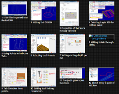
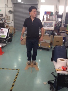
Here are some of images showing i at work
.png)
Conclusion
Firstly, I have learn something new again this week like converting .NC to mastercam. Secondly,the draw on the XY plane and extrude downwards in Inventor is very important. It improved the efficiency and it can so minimize the flipping of parts. Thirdly, the poor finish shown below could be improved with the use of downcut sprial cutters that push the splinters downwards, recommend especially when milling wood. Safety is important all CNC macine always wear a goggle when you doing cutting.