Introduction:
In this assignment i am making pressfit laptop cooling Desk.as usual i have designed and assembled in the CATIA software.It's very useful for working professionals.It is an accessory for laptop computers that helps reduce their operating temperature, which is normally used when the laptop is unable to sufficiently cool itself.
I designed and assembed the model in catia.then following are the PDF files exported from catia. Desk with Fan slot where i am going to fit the 5 volt FAN which will get USB power from laptop.
Figure.1
Following PDF shows the support, i have design the support with 10 degree angle.
Figure.2
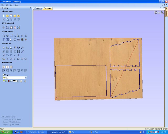
Above PDF parts are imported in the Partwork software. In partwork I can create toolpath required for cutting through the material.then to cut the profile used 3mm solid carbide milling tool.
Figure.3
first I need to cut inner profile otherwise possibility to occure offset due to NO support to the plywood.following figure shows the inner profile cut.
Figure.4
IN partwork there is provision to see the preview of cutting.It shows passes required to cut the material through.following image shows the preview.
Figure.5
Once toolpath is set to inner profile,then we can set toolpath to the outer profile.using 3mm solid carbide toolto cut the profile.
Figure.6
<<<<<<< local
Here need to set tooling parameter like pass Depth,Stepover, SPindle rate and feed rate ,plunge rate.Following image shows the parameter that i set to cut the profile.
=======
Here need to set tooling parameter like pass Depth,Stepover, SPindle rate and feed rate ,plunge rate.Following image shows the parameter that i set to cut the profile.s
>>>>>>> other
Figure.6a
Following figure shows the preview toolpath of the outer profile.
Figure.7
Last saving toolpath so we can generate .sbp file for shopbot. Start the shopbot open sb3 consol to set machine x=0,y=0,z=0 then import the .spb file that was saved in partwork software.
Figure.8
Shopbot is at random position need to set the machine to x=0,y=0 and z=0 without any offset. following figure shows shopbot setting at random location.console shows x,y and z position on bed.Also start toggle switch to turn ON the spindle.
Figure.9
Move axis using arrow keypad on keybord and then Set all the X, Y and Z axis to the zero location from menu Zero and set all axis to zero.
Figure.10
Now load the partfile from the appropriate location.browse to proper location where .sbp file is creaed in partwork software.
Figure.11
Start spindle with Start button.following code is running to cut the part profile.
Figure.12
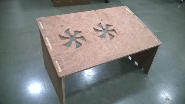
I cut all above part on shopbot but forgot to take snaps while cutting.so here i am adding directly assembled structure.
Figure.13
Cutting files
3D Files
3D Files
PDF1
PDF2
Shopbot1
Shopbot2
Shopbot3