Introduction:
Computer Control Cutting is the use of software to control machine tool and related machinery in the manufacturing of the object. In Computer control cutting assignment i am going to do two assignment
Object 1: Hopper (Designed in CAD Assignment)
Object 2: Worm & Gear Press fit kit using cardboard
In the Computer contol cutting of object 1: Hopper , To cut the part created in CAD Design it was exported in .pdf form for the Epilog Laser then imported to inkscape. set line width to 0.01mm and again save the file in .pdf extension. Figure 1 shows the ready and well arrange file in the inkscape
Figure.1
Our Epilog mini Laser intensity has reduced so I have to set speed=1 Power=100 and Frequecy=5000 to cut the 3mm Acrylic sheet.following Image shows the setting of the Epilog mini laser.
Figure.1a-Setting for cutting Acrylic
Epilog Laser is used to cut the parts. Acrylic transparent marron sheet of 3mm is used for hopper. Figure 2. shows the 2D parts of Acrylic.
Figure.2
After cutting the projection and sloted parts it should be press-fit. I tried to press-fit my object,Following Figure.3 shows the Press-fit of two adjacent part.
Figure.3
Now its time to make full assembly of Hopper.
Figure.4
Successfully fabricated Hopper.
Figure.5
I used Epilog laser to cut the parts. selected Vector cutting method in which setting used were speed=1%,Power=100%, and frequecy=5000%
Figure.5a
Figure.6: Cutstudio file
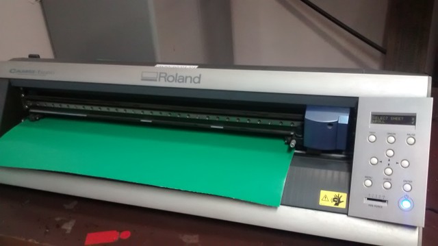
Figure.6: Vinyl Cutting using Roland Gx
Figure.7: Vinyl Cutting using Roland Gx
Hopper Projected files
Hopper Slot files
Final cutting .svg file
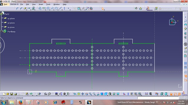
firstly Design this presfit foldable cardboard box. I am fabricating the cardboard Worm and sprocket gear. Here plan is to make foldable kit of worm-gear, it consist the box,Sprocket and worm, worm is driving sprocket which is mounted on cardboard shaft.Following few images are designed in CATIA.
Figure.6
let's design shaft for worm gear. following Figure.7 Shows the 2D design in CATIA
Figure.7
Worm is rested on shaft like a spiral.refer figure no.8
Figure.8
Sprocket Design in catia its ordianry sprocket
Figure.9
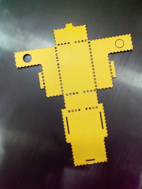
Box is foldable following Figure.10 shows the cut part on the epilog laser.
Figure.10
there was little error in Slot and projection then i modified the file and following is my correct pressfit foldable box
Figure.11
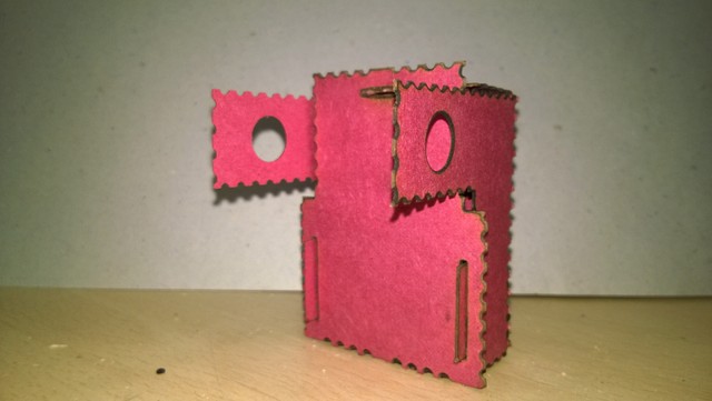
Successfully made a worm gear cardboard model
Figure.12
Profile1 PDF
Profile2 PDF
Profile3 PDF
Gear PDF


