Fab Academy 2013 · Michael Hviid Nielsen
Waag Society's Fablab in Amsterdam
· Lecture 09: Computer Controlled Machining
Lecture 09: Mar 21, 2013
Assignment: Design and make something BIG.
Lecture Notes:
What WE did:
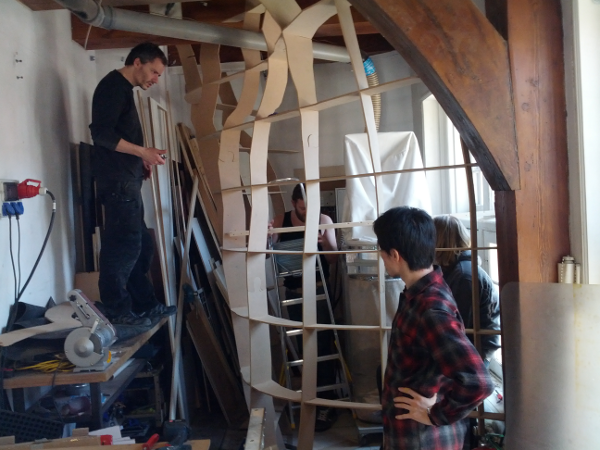
We obtained "special permits" for this weeks assignment. So by collaborative efforts we made "Something BIG". The Amsterdam Fablab was in desperate need for an enclosure/encapsulation of the Shopvac supplying suction and filtering for the Shopbot. We decided that this was our focus for this weeks assignment.
I trawled the net for some inspiration and among a handfull of inspiring design ideas I found this description of an awesome bookshelf designed by "DBD Studio":http://design-milk.com/digitally-fabricated-bookshelf-by-dbd-studio
After we sketched some lines in common we agreed to make an organic shape which at one end would follow or mimick the old wood beams in the wall and ceiling and then turning gradually into a more freeflowing form at the rear end of the room
So we made measurements of the artisanely fitted walls and ceiling at the old Waag in Nieuwmarkt, Amsterdam. Its Amsterdam afterall - so no pressure to be straight here. And this was also the case with the building itself. Not a problem - bent is beautiful afterall.
I made a mock-up of the design constraints in Rhino:
- The maximum measurements of the filtration unit itself
- The walls, ceiling and the old beams of "Pine from
Pommern"
- Access to the filtration unit as well as a breaker box on
the rear wall
On a piece of paper we designed the shape of the dividing
wall we wanted to put up at the floor level and at the
ceiling. Then we traced and lofted these shapes in Rhino.
After that we manipulated the shape to our combined esthatic
values and requirements and finally extruded the surface into
a wall. Then we went on and made cutouts for the Beams in the
ceiling and along one end. We then took that file, exported as
an stl-file, into Autodesk 123D Make where we sliced it up
into pressfit structures along a fitted curve following the
surface.

From there we exported the cut sheets as a dxf-file. We wanted to do the final layout in Illutrator or Inkscape but we soon discovered scaling issued ("measure twice - cut once") and I ended up solving those in Autocad 3ds Max where I also did the final layout on sheets ment for the construction. This could equally well had beed done in other (free) softwares. We discovered that the files exported from 123D Make are exported in inches regardless of the settings in the preferences. We made a 1:10 scale model of the wall in 3 mm mdf on the laser cutter for final approval from our Fablab manager Alex Schraub.
![]()
We then showed the scale model to a local wood supplier who
adviced us on material dimensions. From assessment of
the solidity of the structure as well as material costs we
chose 9 mm mdf sheets. These were then cut on the Shopbot. Due
to the curved organic shape of the wall, the individual pieces
were a bit difficult to layout without material waste. But
since we also need wood to make clamps in the ceiling and
floor - this ended up being minimized to acceptable amounts.
We also altered the pieces which where longer than the mdf
sheets by adding "puzzle/jigsaw joints" at the ends - allowing
them to be connected together.

We then assembled the wall using a nylon hammer following our
markings on the cut pieces - referencing our initial drawing.
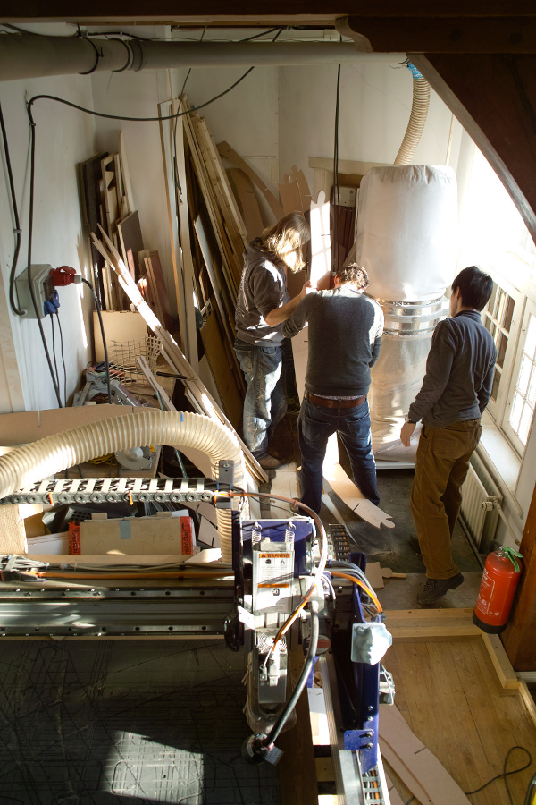
The wall is made so that the verticals actually brace itself between the ceiling and the floor. We used leftover wood to make blocks to fix the wall from being kicked over. These were screwed to the floor and ceiling. The ceiling beams themselves are part of the listed building features so they are left untouched by the design - and actually mimicked at the end of the wall closest to the most prominent one.
The settings used for cutting the 9 mm mdf sheets on the Shopbot was:
Mill: We used a 1/8 inch 4 fluted end millRan the spindle at 30000 RPM and had the machine cut out the parts in three passes (3mm per pass).
We added "Dogboning" in Partworks software in order to cut
into the corners of the press fit parts.
Speeds: We ran the spindle at 30000 RPMs and cut the shapes
in three passes which corresponds to 3.66 mm per pass (milling
depth = 11 mm divided by 3 passes).
Remarks: We used 9 mm mdf due to cost. We originally decided
to use 12 mm but it was simply out of our budget. The 9 mm mdf
where a bit fragile in those sizes and a couple od the broke
at assembly. We used a bit of reinforcement to clamp the
broken spots together.
Milling depth: 11 mm (a bit too much - but we tried 10
mm and in the middle of the sheets this was not quite enough
due to buckling of the mdf).
Things which went wrong:
We would have liked a shorter software toolchain than
"Rhino"-"123D Make"-"Rhino"-"3DS Max" in order to let changes
progress more fluidly. But what we came up with in the time
available actually worked. The scaling issue going from 123D
Make to other software was a bit dissapointing and cost us
some precious time to figure out. Now that we know this it
will be a lot quicker. Another dissapointment was that the
surface of the finished wall ended up less smooth than we
intended. This was due to limitations (memory or bug?) in
Autodesk 123D which we used to slice up the model in ribs. We
had to reduce the surface in Rhino to a lot fewer polygons
than we wanted to in order for it to not crash when slicing
the model. For the next construction I am going to make, I
will use Rhino and Grashopper for slicing up the model. Then
the whole workflow could be realised in curves rather than
poly-lines and the resulting structure would look a lot
smoother.
Things to fix:
We still need to cover the wall surfaces and fix a door. But in the time we had - we actually managed to put up a wall, which we hope will be acknowledged as the largest structure build in the Fablab sofar.