DIGITAL OUTPUT
 - Diodes, are used along
Charlieplexing to control the
current direction following into the
output device. In case of the LEDs,
it acts
- Diodes, are used along
Charlieplexing to control the
current direction following into the
output device. In case of the LEDs,
it acts
as a diode for itself so basically
it needed a resistance to control
the current flowing to it. DC motors
are different where for each motor
you need both positive and
negative supply on the contrary LEDs
need just one input source.
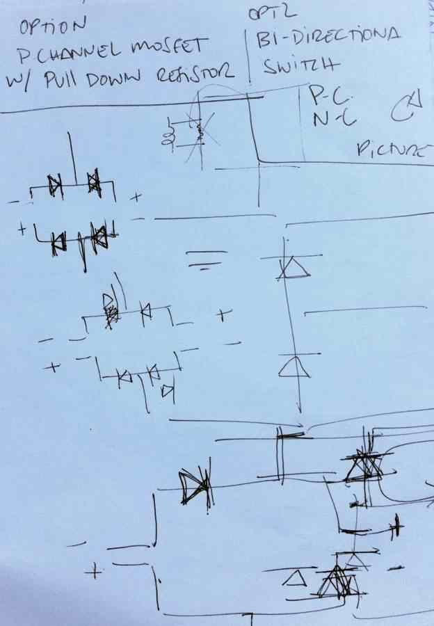
FIGURING OUT HOW TO ADD A
DIODE!
-it
wasn't easy at all for me Luciano
helped me a lot though it, as the
motor
will run in both directions
unlike with the LED case, so after
sketching and
experimenting
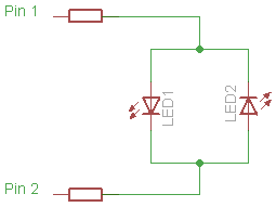
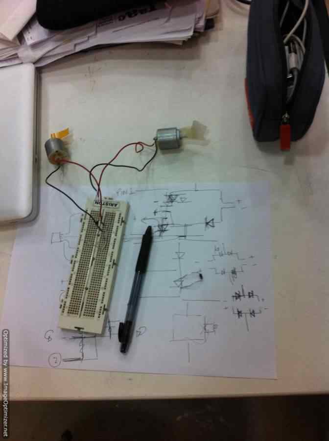
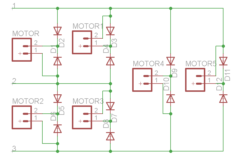
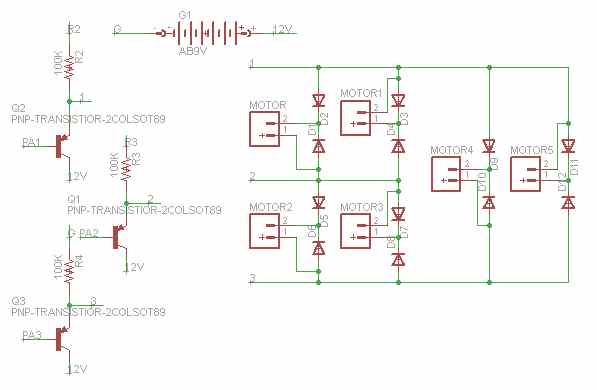
-we figured out that for
each motor we need to add 2 diodes
like the shown
figures. by this we will
control the current flowing though
the motor in both
directions
in one direction coming from one pin at time!
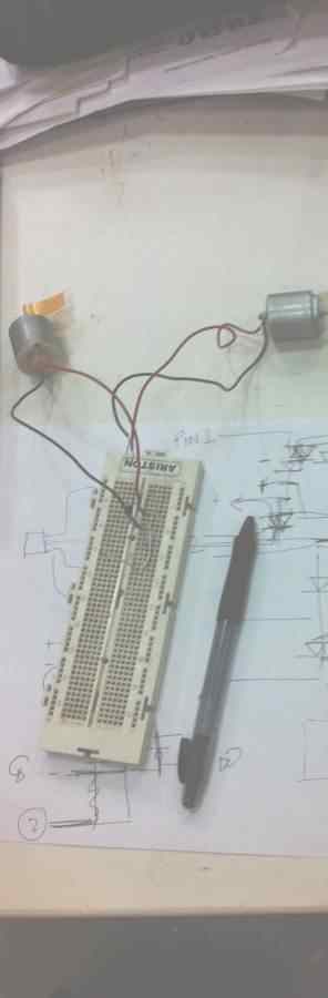
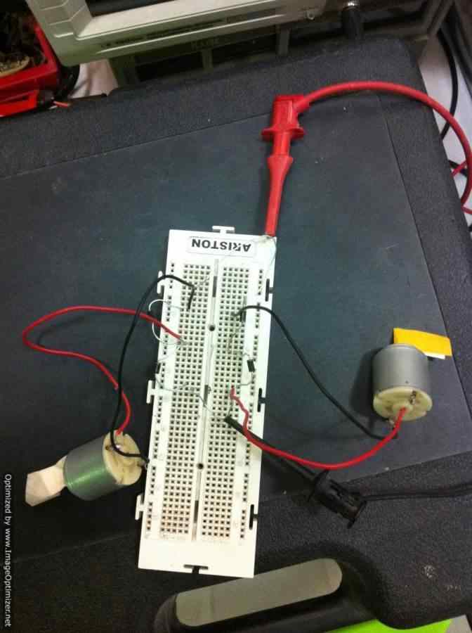
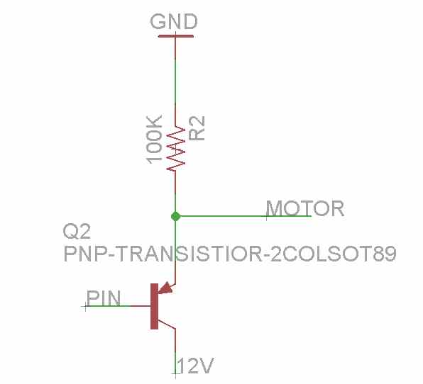
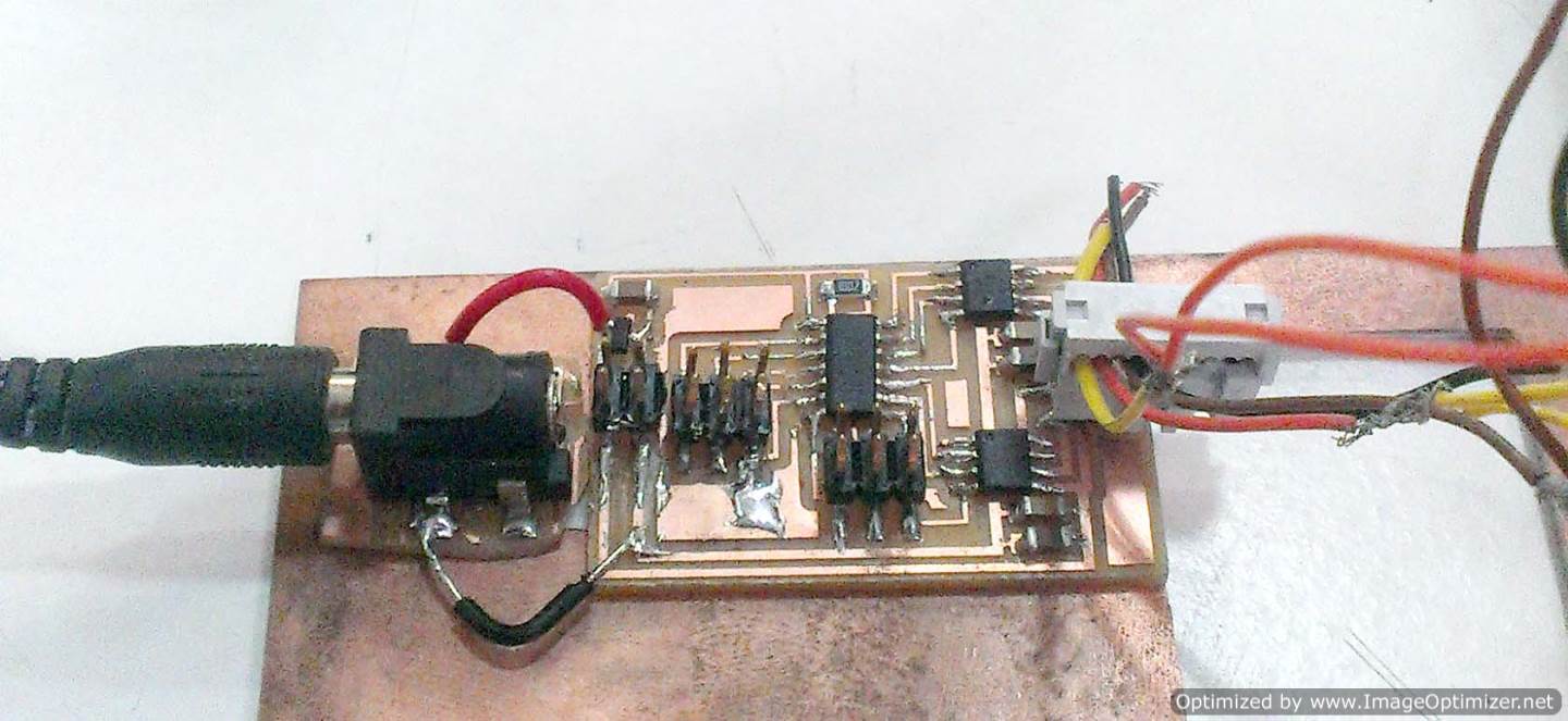
the current in two ways First: is to add P-channel MOSFET along with a pull down resistor ( image1 of the trial is attached) with adding the resistor you
prevent the current from going to ground only when the gate is closed, you will lose a bit of current though but we think the rest is enough to run the motor
Second: is inspired from this link which suggests connecting both PNP and NPN transistors together along with the same pin to the DC motor
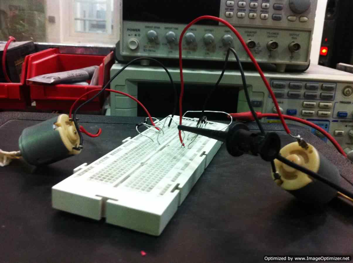
we finally decided to test the normal board without any addition and if not we shall add any of the two options, non of the above trials worked out so i gave up!
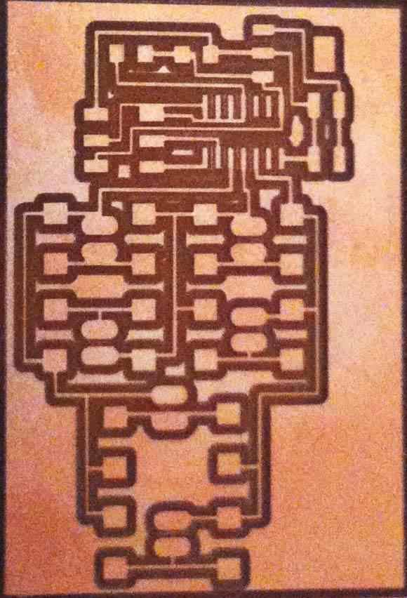

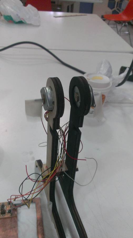
instead,
preparing for my final project i
decided to do the normal stepper board
using two stepper as an out put from
the same board and power
supplied the board with a power jack (watch the video)
>Proposal
>Digital model
>Laser Cutting
>Electronic
production
>3D Scanning
& Printing
>Electronic Design
>Molding & Casting
>Embedded programing
>Computer-controlled
machining
>Input devices
>Composites
>Interface and
application program
>Digital Output