Week 13 - Apr 11th 2012 - Output Devices
Weekly Assignment - Add an output device to a microcontroller board and program it to do something
This week I wanted to make a board that served as a stand-alone project, ie. did not need to be plugged into a computer in order to function. I also wanted to experiment with the charlieplexing technique for driving many LEDs from a minimal number of microcontroller pins. Therefore I decided to make a PCB that incorporated a sensor, and displayed a reading using a charlieplexed array. I designed a circuit in Eagle that included 20 LEDs driven from 5 microcontroller pins, and a MMA1270EG-ND Z-axis accelerometer.
Laying out the PCB design was very difficult, as I wanted the LEDs to be arranged linearly as opposed to in a grid as shown in the example board. Crossing traces were inevitable, so I included some routes (shown in blue) to be on the back of the board.
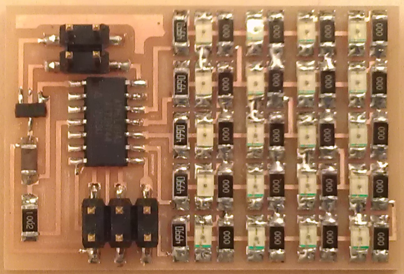
The completed PCB is shown below; traces on the reverse were made with flexible single-cored wire.
The circuit also includes a 4-pin header and 5v regulator so that it can be powered either through the ISP header or from a 9v battery, and two buttons that can be polled by the mcirocontroller.
I programmed the attiny44 using the Arduino IDE. The program is listed below with comments that should explain all of the functionality.
// DDRA bytes for LEDs 1-20
byte portadirs[20] = {B00011000, B00010100, B00010010, B00010001,
B00011000, B00001100, B00001010, B00001001,
B00010100, B00001100, B00000110, B00000101,
B00010010, B00001010, B00000110, B00000011,
B00010001, B00001001, B00000101, B00000011};
// PORTA bytes for LEDs 1-20
byte portasets[20] = {B00001000, B00000100, B00000010, B00000001,
B00010000, B00000100, B00000010, B00000001,
B00010000, B00001000, B00000010, B00000001,
B00010000, B00001000, B00000100, B00000001,
B00010000, B00001000, B00000100, B00000010};
int accelread; // variable to read in voltage from accelerometer
unsigned long lastloop = 0; // variable for timings for demo
void switchon(int led) { // function to switch on one LED
if ((led > 0) & (led < 21)) { // as long as LED is in range 1-20
DDRA = portadirs[led-1]; // set DDRA for two appropriate output pins
PORTA = portasets[led-1]; // set PORTA with appropriate pin high
} else { // if LED not in range 1-20 turn all LEDs off
DDRA = B00000000;
PORTA = B00000000;
}
}
void demo() { // fancy lightshow to ensure everything's working
for (int j = 1; j < 3; j ++) {
for (int i = 1; i < 21; i ++) { // turn on 1 to 20 individually
switchon(i);
delay(30);
}
for (int i = 19; i > 1; i --) { // turn on 20 to 1 individually
switchon(i);
delay(30);
}
}
for (int k = 1; k < 3; k ++) {
for (int j = 1; j < 21; j ++) { // turn on 1 to 20 cumulatively
lastloop = millis();
while((millis() - lastloop) < 30) {
for (int i = 1; i <= j; i ++) {
switchon(i);
}
}
}
for (int j = 1; j < 21; j ++) { // turn off 1 to 20 cumulatively
lastloop = millis();
while((millis() - lastloop) < 30) {
for (int i = 20; i >= j; i --) {
switchon(i);
}
}
}
}
for (int j = 1; j < 5; j ++) {
for (int i = 1; i < 21; i ++) { // turn on 1 and 20, 2 and 19, 3 and 18 etc.
lastloop = millis();
while((millis() - lastloop) < 30) {
switchon(i);
switchon(21-i);
}
}
}
}
void setup() {
digitalWrite(9, HIGH); // activate internal pull-up resistor on pin 3 (button 1)
digitalWrite(10, HIGH); // activate internal pull-up resistor on pin 2 (button 2)
demo(); // play the demo lightshow when first powered on
}
void loop() {
accelread = analogRead(7); // read voltage from accelerometer
switchon(int(float(accelread)/1024*20)); // scale reading to range 1-20 and turn on appropriate LED
if(digitalRead(9) == LOW) { demo(); } // if button 1 pressed, run demo
}
The microcontroller runs a short demo, then continually displays the output of the accelerometer. One of the buttons causes the demo to be replayed, the second is not used but could be used to alter the scaling of the accelerometer reading for instance.
<<< Week 12
Week 14 >>>


