Week 11 - Mar 28th 2012 - Input Devices
Weekly Assignment - Measure something: add a sensor to a microcontroller board and read it
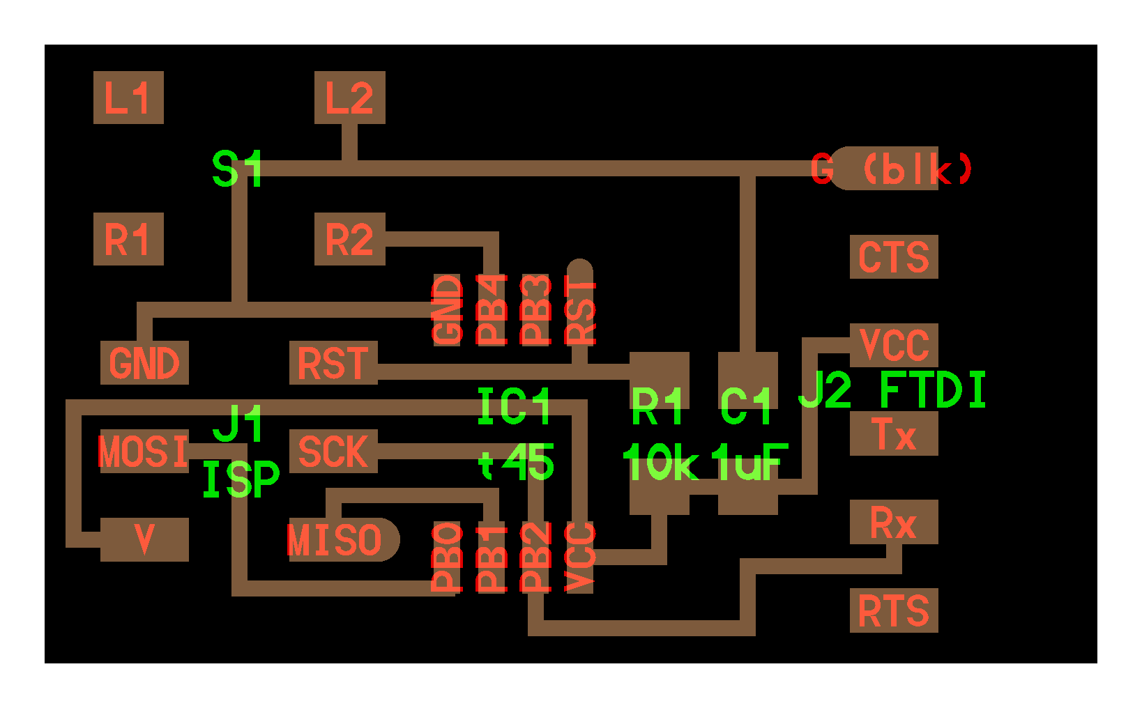
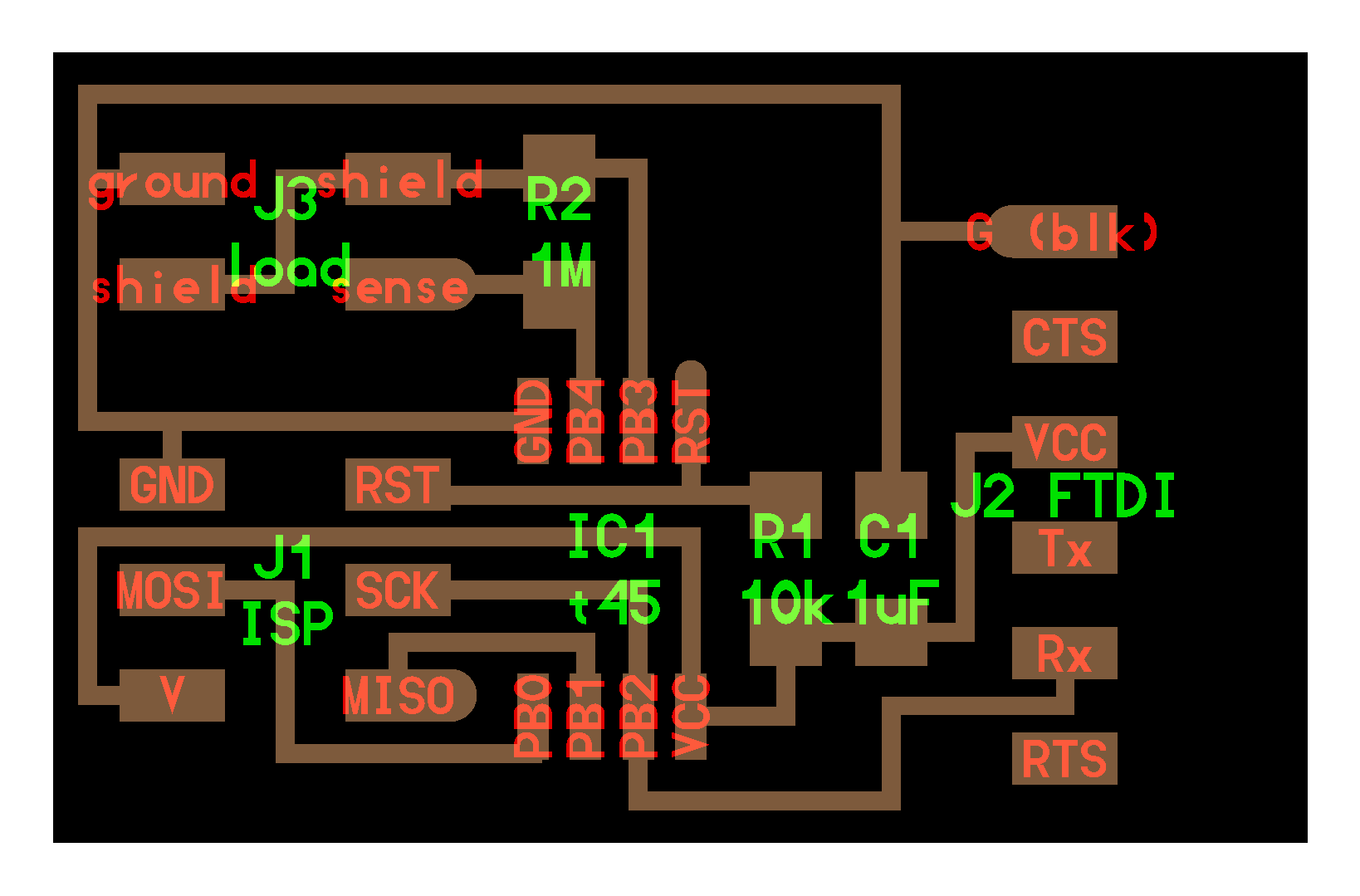
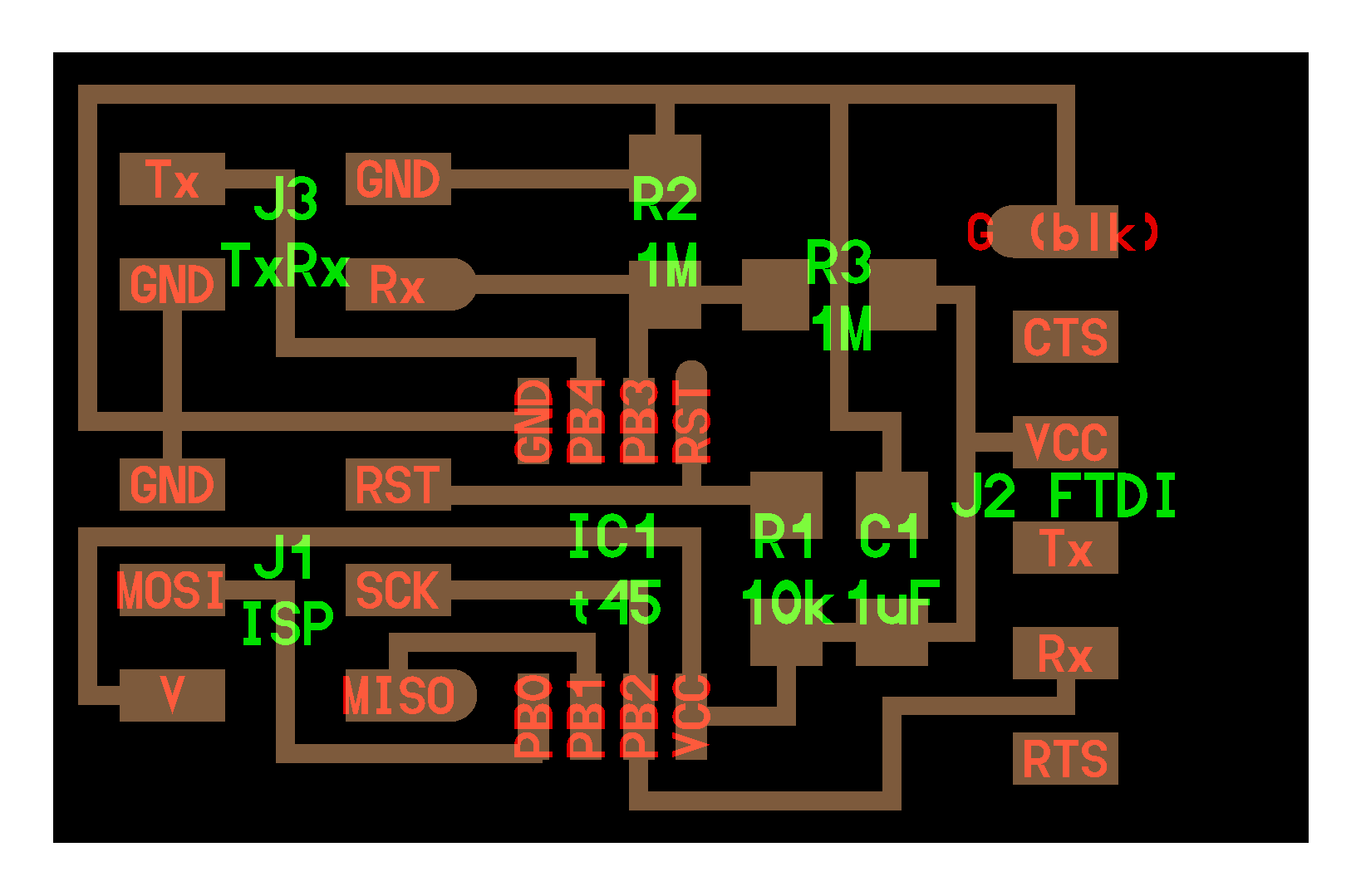
Lots of sensors this week. Reading them was achieved in several ways; simply polling pin voltages, reading changes in resistance based on altering conditions (light, temperature), or detecting altering capacitance via the DC step response method. In order to understand these I fabricated six of Neil's example boards; button, light, temp, sound, step, and txrx. The only changes I made to the circuit boards was to add the names which were then milled by the Modela, and to compile them all into one trace and interior .png image so they were all milled at the same time. In addition, as a lab we ran out of the pin header we use for ftdi headers so had to improvise, and ended up using 2x5 vertical headers. These worked well because only 5 of the 6 ftdi pins are used, and also the unused side of the header could be soldered to the unused copper on the outside of the board providing additional stability.


Following the instructions in Anna's tutorial here I got each board working using Neil's various python scripts (I think I might need to learn python? It seems to come up a lot. Also, Neil's .cad language for circuit boards although maybe that's for another week) on the mac. They all worked fine, with the most suprising being the temp board - just breathing on the thermistor caused an instant response that then faded very quickly; I was expecting a much more delayed effect! This is presumably down to the rectifier bridge employed in the circuit allowing detection of very slight changes in resistance. Also, the directionality of the phototransistor (this is the part we use in our lab) was very noticeable - I don't think this particular component would be ideal for a general light/dark sensor, for instance.