Eagle Files
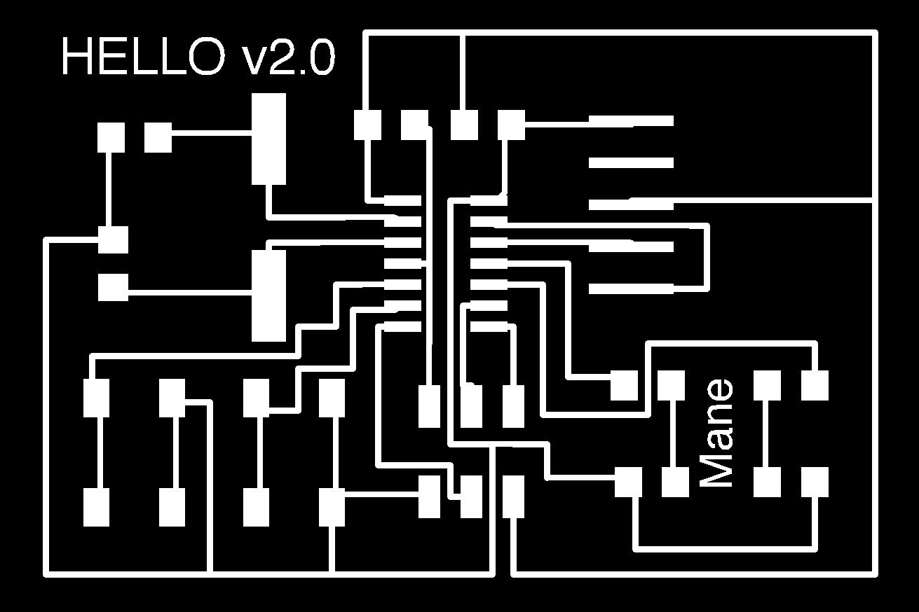
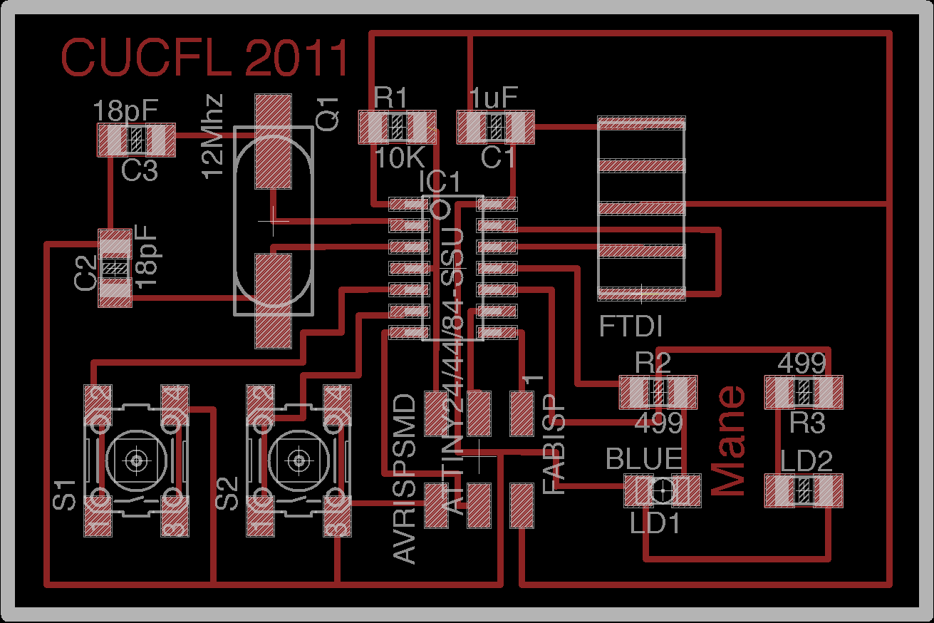
For this week's assignment we needed to modify the Echo_Serial_Hello_world board by adding 1 push button switch and one LED. I added 2 of each to my board and I also made pins to accommodate a speaker in the future. The idea is to be able to use the 2 push buttons to enter a sequence or high and low values (ON/OFF) and if the code is correct (matches the one in the code) then the leds will flash the sequence and the speaker with go off.
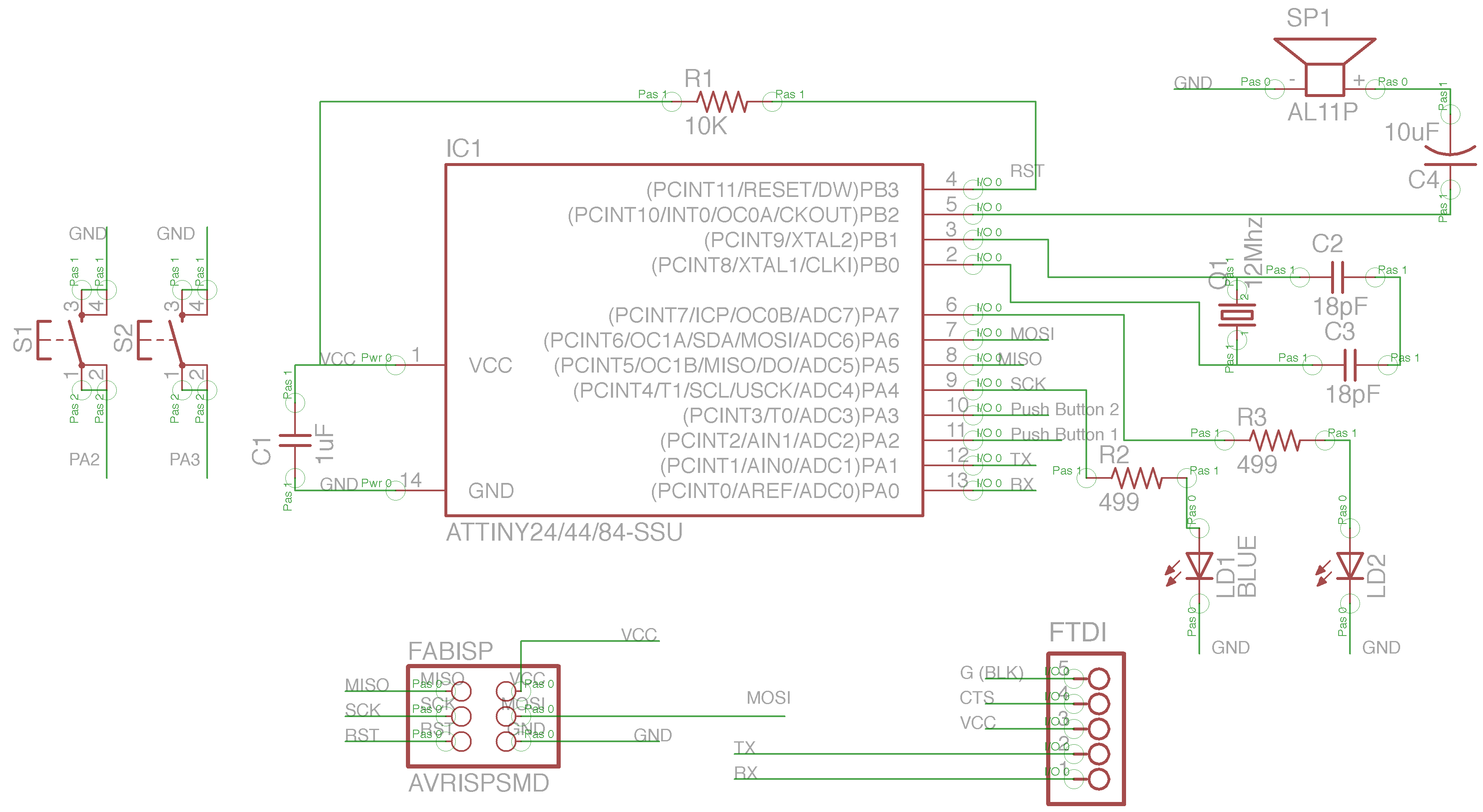
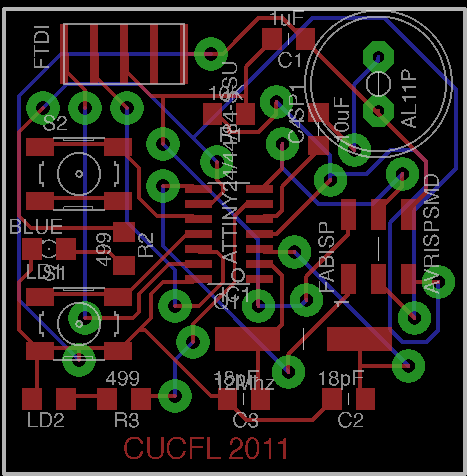
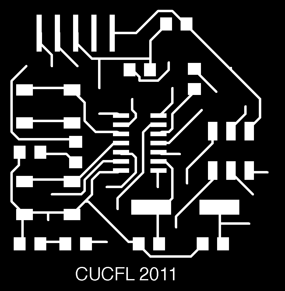
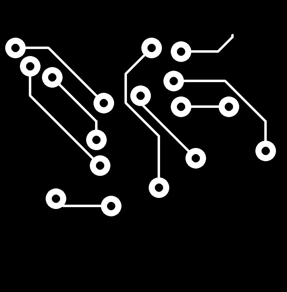
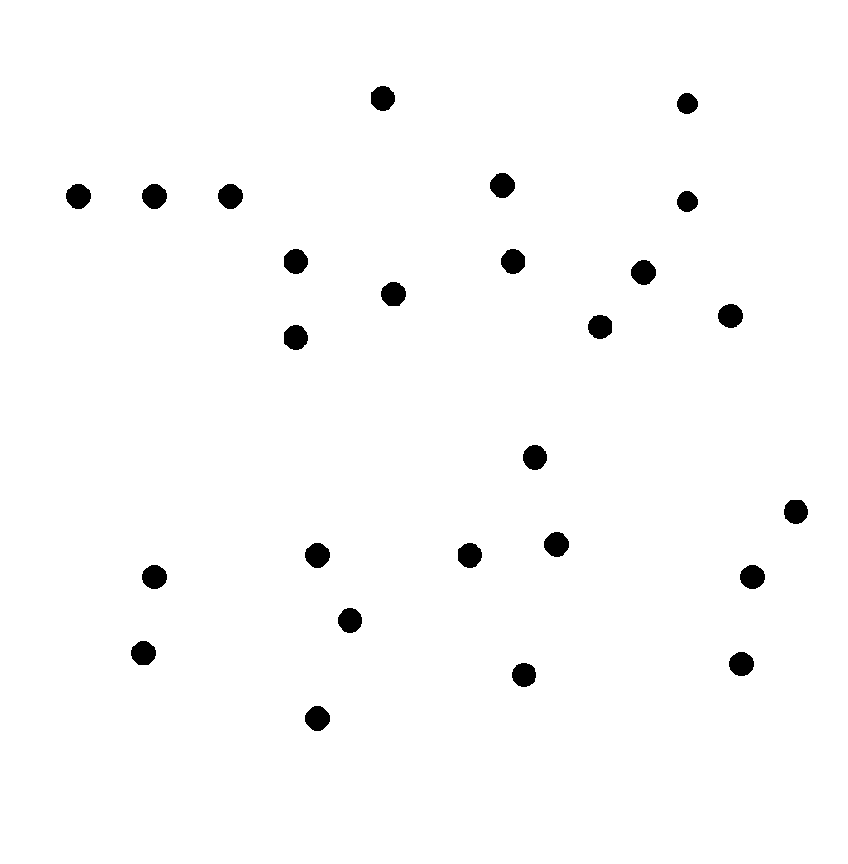
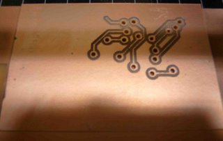
Schematic diagram of the circuit Board layout. Top layer is red, bottom layer is blue and the vias and pads are in green
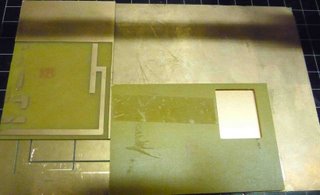
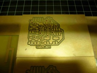
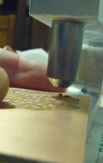
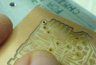
Cutting the traces on the Modela
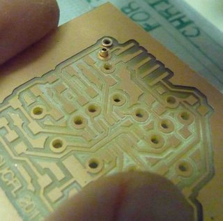
I cut first the top layer of the board and then the holes and pads. This made it easer to align the bottom layer since I used the holes to align the board to match exactly the top layer. One thing to remember is that the bottom layer needs to be mirrored horizontally (I did this using GIMP).To align the bottom board I mirrored the vias_and_pads.png file and I “pretended” to cut the vias again, but I used a small size bit and set my z value on the FAB Modules to something very small (like -0.1mm) this way I did not cut any material but I was able to see if I had the board aligned correctly.
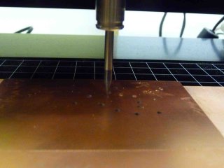
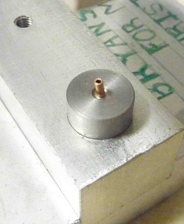
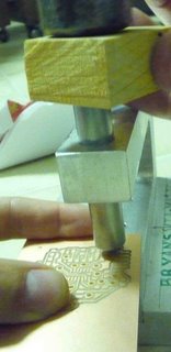
Inserting the vias.
The via-maker, is a tool my husband made for me this past Christmas as a gift. I finally had an opportunity to use it. Bellow are the image that try to explain how it works. Unfortunately we found a fault, I cannot make the vias to close to each other. This is something that will be fixed soon (I hope). So for this time around I still had to manually solder some of the vias.
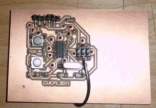
Populated Board
Programming the Board
Using Assembly Language (Hello v2.0)
On a side note I found a couple of routing mistakes on my v1.0 so remade the Hello Board and here are the new eagle files)
To program the board copy the following code (red script) into a text document and name it hello.asm
; Modified.Hello.Echo.Blink LED.44.asm
; blink LED when button is pressed
; Code Created At FAB ACADEMY Urbana
; by Shawn Wallace & Elliot Clapp
; Last Modified 03/21/2011 - Mercedes Mane
; Permission granted for experimental and personal use;
.device attiny44
.org 1
cbi DDRA, 7 ;check bit instruction (button1, right)
sbi DDRA, 3 ; set bit instruction (left blue led)
cbi DDRB, 2 ;check bit instruction (button2, left)
sbi DDRA, 2 ; set bit instruction (right green led)
loop:
sbic PINA,7
sbi PORTA, 3
sbis PINA,7
cbi PORTA, 3
sbic PINB,2
sbi PORTA, 2
sbis PINB,2
cbi PORTA, 2
rjmp loop
Open a command window and navigate to the folder where you save the hello.asm file
type the following (sans enter):
gavrasm hello.asm (enter)
This will generate the hello.hex file that you will flash to the Hello board.
If you do not have gavrasm you can get it here:
Connect the ubstiny to your computer and the target board (the Hello Board) to the FabISP board.
Burn the fuses by typing the following:
avrdude -p t44 -c usbtiny -U lfuse:w:0xFF:m (for 12Mhz oschillator)
avrdude -p t44 -c usbtiny -U lfuse:w:0x7E:m (for 20Mhz oschillator)
Type the following to flash the hello.asm to the target board.
avrdude -p t44 -c usbtiny -U flash:w:hello.hex (enter)
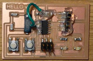
For my board, when I press the right button the right led turns green, and when I press the left button the left led turns blue.
Fabhello at work. Programmed using FabISP and assembly language.
Make it blink blue and green
Use these commands to make the hex file and flash it to the Hello board.
make -f hello_blink.make
sudo make -f hello_blink.make program-usbtiny-fuses
sudo make -f hello_blink.make program-usbtiny