
PROJECT PROPOSAL
I've been listening to tunes on my Macbook's audio system for a couple years now. Not great, but good enough. Over the next six months I want to build my own set of speakers. I'd like to make them hi-def, wireless, have programmed LED lights that change color based on frequency. As I learn new things, I'll be looking for cool bells and whistles to add to this project. Below is a schematic I showed in class.
PROJECT MANAGEMENT
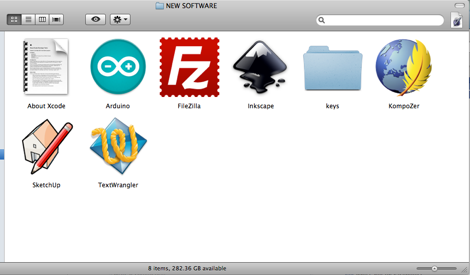
This week I downloaded and set up the software we will be using in the upcoming weeks. I tinkered with Terminal, Kompozer, Filezilla and Mercurial to get this website up and running. Using Terminal and Mercurial I connected and synced with the MIT archives. Got stuck a couple of times, but now that it's set up it should be much easier to connect. These are the commands I will use each week:
     hg add
     hg commit -m "add message"
     hg pull
     hg push
     hg merge
Next, I used Kompozer, an open source What-you-see-is-what-you-get (WYSIWYG) software, to personalized this website. Anna Kazuinas France provided a simple template and taught me to generate basic HTML + CSS.
COMPUTER-AIDED DESIGN
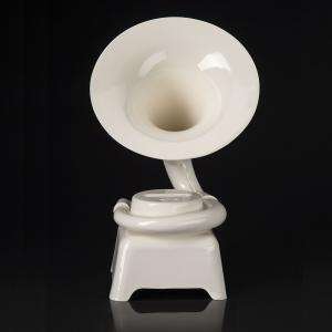
The images above are my first experiments with Google Sketch Up. This is how I envision my speaker set. The exterior materials will be malleable (not certain what yet). The white circles towards the bottom will be covered with vellum and surrounded by LEDs in the interior. The infrastructure will be built using masonite or plywood.
PRESS FIT DESIGN
I played with the laser cutter. Mostly I was looking to create a that repeated and interlocked. In addition, created a small model for a coat rack that I'm hoping to make with the shopBot.
ELECTRONIC PRODUCTION
This Fab ISP isn't functional yet. At first, I accidentally created a bridge between two traces on the board using solder. Once I cleaned that up, I tested the connection using a multimeter. There was one pin that was floating. Currently, when I connect to the programmer it flashes. I plan to work on it further.
UPDATE: Wasn't able to figure out the problem with the last board so I started over. I programmed the board using Terminal. And now, I able to use it to program other boards.
COMPUTER-CONTROLLED MACHINING
The Fab Academy at AS220 went on a field trip to Keeseh, a community woodshop on the west side of Providence, RI. Asher, a founding member, gave us a tour and the opportunity to use the shopBot to create individual projects. Using a vector file I created in Inkscape, Asher created a new file using PartWorks. The file created told the machine which area to mill first, what type of cuts to make and how deep to cut (z axis). My file took an hour and twenty minutes to cut, and resulted in new coat rack for the AS220 Labs.
ELECTRONIC DESIGN
COMING SOON
MOLDING, CASTING + COMPOSITES
I was hopeful when I started this unit, but this assignment tested my patience at each step. Why? Sometimes machines don't or can't do what you ask them. No reason. They just don't. So you reboot. Try again. And voila- it works this time!
I started with an abstract image I took of a high-relief ceiling. I used the fab modules to create a filepath that the milling machine could use to create a wax mold. The first hiccup: it didn't work. The screen froze each time. It turned out that that instead of the computer sending the information to the milling machine, it was sending it to the usb port. After Anna worked her magic and fixed the issue. The next day I was able to begin milling.
I set the machine to mill a new layer every (.5 millimeters). This meant my 3" x 5" x 1" design would take 8 hours to render. The milling began. For the first two hours I checked in on it every 15 mins. Then it was time to leave for the night. I was nervous but couldn't stay later. That night I worried about it from home. I woke up early and stopped in the Labs before work. The machine was quiet but the job wasn't done. In the middle of the night the bit loosened to the point that it embedded itself into a corner of the mold and separated from the head. Ugh.
I reattached the bit and started the job over. Another 8 hours. This repeated twice before the milling machine rendered my project in full.
With my mold in order, part two was to cast a rubber mold compound that would cast my final product. I used a 90watt bulb to cure the solution. It took approx. 15 minutes, and was successful.
The final stage: I poured a white plastic solution into the mold and waited an hour. When it was time to see the final product. The plastic wouldn't detach from the rubber. After much prodding and twisting I was able to set it free. In the process I destroyed both the mold and the cast (and my heart).
EMBEDDED PROGRAMMING
This week I created an echo board.
I milled and stuffed the board.
Then I downloaded these files:
hello.ftdi.44.echo.c, hello.ftdi.44.echo.c.make hello.ftdi.44.echo.c.hex
I program the using Terminal and these 3 commands:
make -f hello.ftdi.44.echo.c.make
sudo make -f hello.ftdi.44.echo.c.make program-usbtiny-fuses
sudo make -f hello.ftdi.44.echo.c.make program-usbtiny
This video was taken several months after I made the board. It was acting a little funny, but still worked.
3D SCANNING + PRINTING
Inspired by a online video on milk scanning, I set out to create my own. I downloaded OpenFrameworks here.
I assembled a webcam onto a crate,and placed my object in a dish underneath the camera. I chose two objects for distinctive shapes, a small statue of a Buddha and a whisk.
OpenFrameworks made the whole process much easier. The software allows you to capture images over time while it changes the gradient levels from dark to light. This meant that after my initial set-up, I just paused the program every 15 seconds, captured an image and poured a 1/2 cup of milk into the dish where my object lay. The images compile in a separate folder. The interface for OpenFrameworks shows you how your final scan looks at each stage. Easy!
Printing:
I started by creating a 3D model in GoogleSketch up.
I then downloaded ReplicatorG and import my sketch up file.
ReplicatorG created a filepath for our Cupcake CNC machine.
I sent the file to be printed which was estimated to take about an hour and twenty minutes.
Here are the images.
INPUT DEVICES
I decided to make my own step response board and touchpad. Here's what I did:
I milled and stuffed the board
I created a touchpad using two sheet of copper and wire.
I downloaded the python. step.45.py
Then I found the serial port it was connected to by typing into the terminal ls /dev/tty*
This serial port was the one that was connected was: /dev/tty.usbserial-FTDOMMCV
I navigated to the directory the file was in and ran this command: python hello.step.45.py /dev/tty.usbserial-FTDOMMCV
I then discover this error:
Traceback (most recent call last):
File "hello.step.45.py", line 16, in <module>
import serial
ImportError: No module named serial
I needed to download pyserial to enable python to connect to the serial port.
http://sourceforge.net/projects/pyserial/files/pyserial/2.5/pyserial-2.5.tar.gz/download
I unzipped the file and looked at the Read Me for instructions on how to install.
I typed: python setup.py install to install and had no error
Then I typed this command again:
python hello.step.45.py /dev/tty.usbserial-FTDOMMCV
Here are some pictures of my process, and a video was my final results:
INTERFACE + APPLICATION PROGRAMS
I created this installation, in collaboration with artists Alicia Dolabaille and Camila Morales, using 1250 cups, 2068 binder clips, two arduinos, one sound sensor and 20 brite LEDs. Our focus was to use objects, sound and light to simulate an underwater environment that is inspired by the movement of Bioluminescent Aequorea Jellyfish. The sound sensor received analog data to initiate 4 stages of our "creature’s" mood: happy/normal state (fading blues and purples), irked/alert state (a red flicker), really irked/warning state (red + noisy), and outta here/hidind state (shuts off completely). We used fishing line to raise spherical structures from the ground, up the wall and onto the ceiling-- this helped create a mood of a living entity that embodies the space.
The installation is made up of 2 Arduinos that control 10 shiftbrites LEDs each. A sound sensor is attached to each Arduino. The Arduino nearest the floor is equipped with a single, simple motor that vibrates in when the ‘creature’ is really irked. Each string of LEDS is attached consecutively by of six wires which are hidden under a layer on white tape. Fishing lines, tape, screws and hot glue hold the cups + clips in place.
To experience the installation, viewers are welcomed to enter a small, dark room. They are greeted with pulsating spheres on the floor, along the wall and suspended from the ceiling. The organism seems to live peacefully, emitting colors that fades through shades of blue and green. The sound of footsteps or talking disturbs the creature and then it begins to flicker shades of red. Get a bit louder then the creature steps into its warning state and emits a vibrating sound while turning bright red. Finally, if still disturbed, the viewers are left in the dark; the creature enters its hiding mode.
Here's the Arduino code:
#define clockpin 13 // CI _yellow
#define enablepin 10 // EI _green
#define latchpin 9 // LI _blue
#define datapin 11 // DI _white
#define RED 0
#define GREEN 1
#define BLUE 2
const int NumLEDs = 10; //10 max per string
int LEDChannels[NumLEDs][3] = {0};
int SB_CommandMode;
int SB_RedCommand;
int SB_GreenCommand;
int SB_BlueCommand;
int sensorPin = 0; // select the input pin for the sound sensor
int sensorValue = 0; // variable to store the value coming from the sensor
int respond; //variable to control the delay <<<<< change name !!!!!
int motorOnePin = 3; // testing the motor setting it up at this pin
int normalThreshold = 50;
int alertThreshold = 80;
int warningThreshold = 120;
int hidingThreshold = 150;
void setup() {
Serial.begin(9600);
pinMode(datapin, OUTPUT);
pinMode(latchpin, OUTPUT);
pinMode(enablepin, OUTPUT);
pinMode(clockpin, OUTPUT);
pinMode (motorOnePin, OUTPUT); //again testing motorOne
// ShiftBrite setup:
SPCR = (1<<SPE)|(1<<MSTR)|(0<<SPR1)|(0<<SPR0);
digitalWrite(latchpin, LOW);
digitalWrite(enablepin, LOW);
}
void SB_SendPacket() {
if (SB_CommandMode == B01) {
SB_RedCommand = 120;
SB_GreenCommand = 100;
SB_BlueCommand = 100;
}
SPDR = SB_CommandMode << 6 | SB_BlueCommand>>4;
while(!(SPSR & (1<<SPIF)));
SPDR = SB_BlueCommand<<4 | SB_RedCommand>>6;
while(!(SPSR & (1<<SPIF)));
SPDR = SB_RedCommand << 2 | SB_GreenCommand>>8;
while(!(SPSR & (1<<SPIF)));
SPDR = SB_GreenCommand;
while(!(SPSR & (1<<SPIF)));
}
void WriteLEDArray() {
SB_CommandMode = B00; // Write to PWM control registers
for (int h = 0; h<NumLEDs; h++) {
SB_RedCommand = LEDChannels[h][0];
SB_GreenCommand = LEDChannels[h][1];
SB_BlueCommand = LEDChannels[h][2];
SB_SendPacket();
}
delayMicroseconds(15);
digitalWrite(latchpin,HIGH); // latch data into registers
delayMicroseconds(15);
digitalWrite(latchpin,LOW);
SB_CommandMode = B01; // Write to current control registers
for (int z = 0; z < NumLEDs; z++) SB_SendPacket();
delayMicroseconds(15);
digitalWrite(latchpin,HIGH); // latch data into registers
delayMicroseconds(15);
digitalWrite(latchpin,LOW);
}
void setAllLEDs(int color, int value) {
for (int x=0; x < NumLEDs; x++) {
LEDChannels[x][color] = value;
}
}
void loop() {
//fades in
for (int i = 0; i <= 341; i++) {
sensorValue = analogRead(sensorPin); // read the value from the sensor:
//state one: normal
if (sensorValue <= normalThreshold) {
Serial.println(" normal");
respond = 10;
analogWrite(motorOnePin, 0);
//setAllLEDs(int color, int value): calling function
setAllLEDs(RED, 10);
setAllLEDs(GREEN, 2*i);
setAllLEDs(BLUE, 2*i);
}
//state two: alert - blinks red NO motor
if (sensorValue > normalThreshold && sensorValue <= alertThreshold) {
Serial.println(" alert");
respond = 6;
analogWrite(motorOnePin, 0);
//setAllLEDs(int color, int value): calling function
setAllLEDs(RED, 2*i);
setAllLEDs(GREEN, 0);
setAllLEDs(BLUE, 0);
}
//state three: warning - blinks red AND motor on
if (sensorValue > alertThreshold && sensorValue <= hidingThreshold) {
Serial.println(" warning");
respond = 4500;
analogWrite(motorOnePin, 154);
//setAllLEDs(int color, int value): calling function
setAllLEDs(RED, 1023);
setAllLEDs(GREEN, 0);
setAllLEDs(BLUE, 0);
}
//state four: hiding state - shut off
if (sensorValue > hidingThreshold) {
Serial.println(" hiding");
respond = 6000;
analogWrite(motorOnePin, 0);
//setAllLEDs(int color, int value): calling function
setAllLEDs(RED, 0);
setAllLEDs(GREEN, 0);
setAllLEDs(BLUE, 0);
}
// print the results to the serial monitor:
Serial.print(" /sensor = " );
Serial.println(sensorValue);
WriteLEDArray();
// wait some milliseconds before the next loop
// to change the speed that colors change and how frequently sensor is read
delay(respond);
} // end For loop
}
Here is a video of the installation.
MECHANICAL DESIGN
We did this as a class. The images are here.
OUTPUT DEVICES
This week learned about charlieplexing. Here's how I did it:
First, I milled and stuffed the board.
Then I modified the C file to manipulate which LED would light.
Here's the code:
//
//
// hello.array.44.c
//
// Charlieplex LED array hello-world
//
// Neil Gershenfeld
// 11/13/10
//
// (c) Massachusetts Institute of Technology 2010
// Permission granted for experimental and personal use;
// license for commercial sale available from MIT.
//
#include <avr/io.h>
#include <util/delay.h>
#define output(directions,pin) (directions |= pin) // set port direction for output
#define input(directions,pin) (directions &= (~pin)) // set port direction for input
#define set(port,pin) (port |= pin) // set port pin
#define clear(port,pin) (port &= (~pin)) // clear port pin
#define pin_test(pins,pin) (pins & pin) // test for port pin
#define bit_test(byte,bit) (byte & (1 << bit)) // test for bit set
#define led_delay() _delay_ms(1) // LED delay
#define led_port PORTA
#define led_direction DDRA
#define A (1 << PA1) // row 1
#define B (1 << PA2) // row 2
#define C (1 << PA3) // row 3
#define D (1 << PA4) // row 4
#define E (1 << PA5) // row 5
char row1 = 31;
char row2 = 31;
char row3 = 31;
char row4 = 31;
char row5 = 31;
void updateScreen(){
if ((row1 >> 3) & (0x01)) {
flash(B, A, 1);
}
if ((row1 >> 2) & (0x01)) {
flash(C, A, 1);
}
if ((row1 >> 1) & (0x01)) {
flash(D, A, 1);
}
if ((row1) & (0x01)) {
flash(E, A, 1);
}
if ((row2 >> 3) & (0x01)) {
flash(A, B, 1);
}
if ((row2 >> 2) & (0x01)) {
flash(C, B, 1);
}
if ((row2 >> 1) & (0x01)) {
flash(D, B, 1);
}
if ((row2) & (0x01)) {
flash(E, B, 1);
}
if ((row3 >> 3) & (0x01)) {
flash(A, C, 1);
}
if ((row3 >> 2) & (0x01)) {
flash(B, C, 1);
}
if ((row3 >> 1) & (0x01)) {
flash(D, C, 1);
}
if ((row3) & (0x01)) {
flash(E, C, 1);
}
if ((row4 >> 3) & (0x01)) {
flash(A, D, 1);
}
if ((row4 >> 2) & (0x01)) {
flash(B, D, 1);
}
if ((row4 >> 1) & (0x01)) {
flash(C, D, 1);
}
if ((row4) & (0x01)) {
flash(E, D, 1);
}
if ((row5 >> 3) & (0x01)) {
flash(A, E, 1);
}
if ((row5 >> 2) & (0x01)) {
flash(B, E, 1);
}
if ((row5 >> 1) & (0x01)) {
flash(C, E, 1);
}
if ((row5) & (0x01)) {
flash(D, E, 1);
}
}
void flash(uint8_t from, uint8_t to, uint8_t delay) {
//
// source from, sink to, flash
//
static uint8_t i;
set(led_port,from);
clear(led_port,to);
output(led_direction,from);
output(led_direction,to);
for (i = 0; i < delay; ++i){
led_delay();
}
input(led_direction,from);
input(led_direction,to);
}
void led_cycle(uint8_t number, uint8_t delay) {
//
// cycle through LEDs
//
uint8_t i;
for (i = 0; i < number; ++i) {
flash(B,A,delay);//command 1st LED
flash(C,A,delay);//2
flash(D,A,delay);//3
flash(E,A,delay);//4
flash(A,B,delay);//5
flash(C,B,delay);
flash(D,B,delay);
flash(E,B,delay);
flash(A,C,delay);
flash(B,C,delay);
flash(D,C,delay);
flash(E,C,delay);
flash(A,D,delay);
flash(B,D,delay);
flash(C,D,delay);
flash(E,D,delay);
flash(A,E,delay);
flash(B,E,delay);
flash(C,E,delay);
flash(D,E,delay);
}
}
int main(void) {
//
// set clock divider to /1
//
CLKPR = (1 << CLKPCE);
CLKPR = (0 << CLKPS3) | (0 << CLKPS2) | (0 << CLKPS1) | (0 << CLKPS0);
//
// main loop
//
while (1) {
row1 = 15;
row2 = 4;
row3 = 2;
row4 = 4;
row5 = 15;
int i;
for (i = 0; i < 50; i++) {
updateScreen();
}
row1 = 0;
row2 = 7;
row3 = 10;
row4 = 7;
row5 = 0;
for (i = 0; i < 50; i++) {
updateScreen();
}
row1 = 0;
row2 = 5;
row3 = 10;
row4 = 15;
row5 = 0;
for (i = 0; i < 50; i++) {
updateScreen();
}
row1 = 9;
row2 = 9;
row3 = 15;
row4 = 9;
row5 = 9;
for (i = 0; i < 50; i++) {
updateScreen();
}
}
}
The final product spells my first name. Watch the video.
NETWORKING + COMMUNICATIONS
This week I created a bus to network information.
First, I milled and stuffed the boards.
Then I modified each c and make file because I used ATTINY 85s instead of a 45s.
I programmed each board using Terminal and the make and sudo commands.
MACHINE DESIGN
We did this unit as a class. The images are here.
APPLICATIONS AND IMPLICATIONS
COMING SOON.
PROJECT DEVELOPMENT
COMING SOON.
INVENTION, INTELLECTUAL PROPERTY AND BUSINESS MODELS
COMING SOON.