Week #17 || Mechanical Design, Machine Design
Software used:
Machine used:
Setbacks:
1. Conception
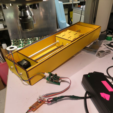
For the machine design assignment I joined forces with my colleague Martin Gutmann. We took up the idea of our teacher Ferdi to give an old machine design assignment for FabLabBCN a new life; the ‘fab lathe’ by our co-teacher Santi who did Fab Academy in 2012. Click here to see his page on this assignment.
We were going to adjust the design to integrate our Dremel tool onto the lathe as the cutting device. Also we changed on the motors for a stepper motor, for better control of the lathe spindle speed. Martin milled an extra pocket into the lathe body to hold this motor. My first task was to design an adapter to hold the Dremel.
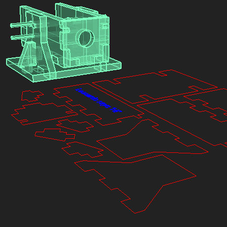
We will not end up using the bodies of the machine designed by Nadya, but just the motors and the electronic nodes to controll the lathe. So we are still keeping the same modular principle of her design.
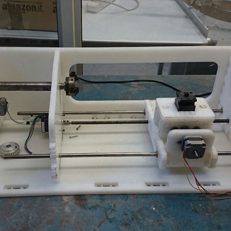
The picture on the left shows one of Nadya Peek's applications to her design, and on the right is the lathe designed by Santi's group. Both mechanisms are compatible with each other, so the lathe is perfectly adaptable to work with Nadya's motor control modules.
2. Reconfiguration and adaptation
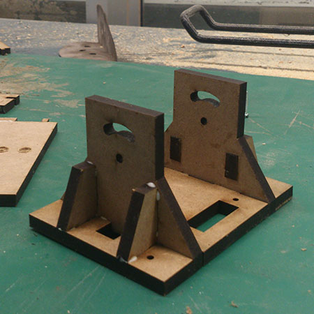
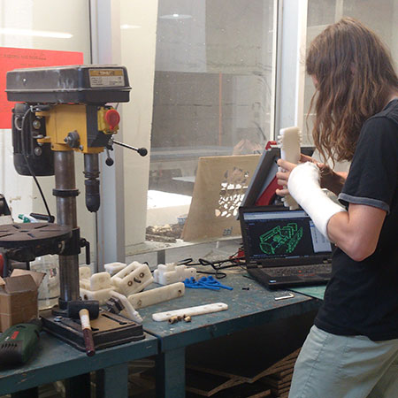
As Martin was making the modification in the lathe to add the stepper motor, my first task was to design and make an adapter for the Dremel. First I tried a design for the 3D printer, but it proved too unstable after trying it out. It was designed to be fixed at two points, allowing a 30 degree rotation.
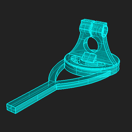
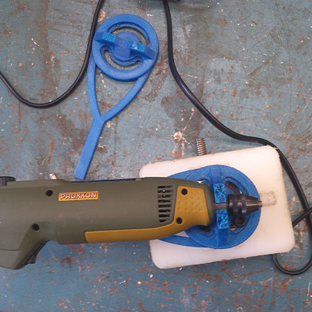
The print failed twice, but it was already obvious the piece was not strong enough to support the weight of the Dremel, so me and Martin decided to get ahead and design a new piece made of wood. We took the same mechanism for rotation as I had used in the previous piece. I sat together with Martin during the design process, Martin described his idea of the box based design and made measurements on the dremel and lathe, and I translated that into the 3D design in Rhino in realtime, and made nesting when we were done with that. We cut it on the Trotec 400 laser, and it was a perfect fit. We just needed to remake it once, to be a bit higher to get a bigger angle of rotation, now set at 60 degrees.
3. Move!
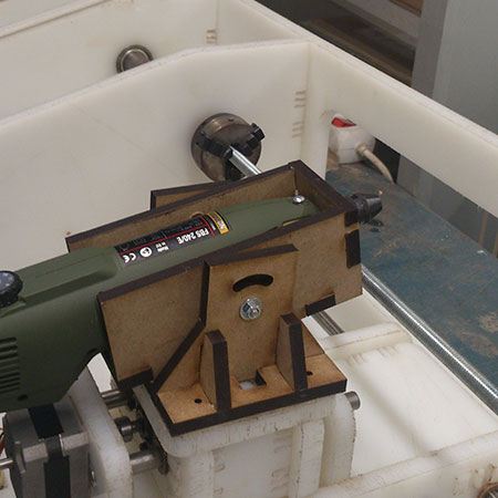
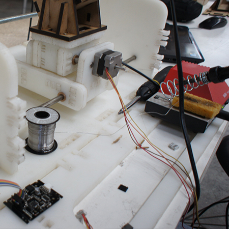
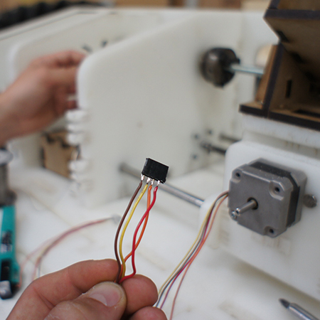
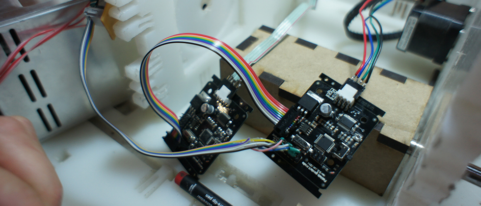
The next step is to integrate the nodes with the motors we are using, to make the lathe move! Me and Martin spent all day first assembling the lathe together. Then Martin soldered the wires to the nodes and placed and connected them to each motor, and took care of the mechanics. After Ferdi showed us the 'how to', I then went through the programming process in Ubuntu to set up the nodes, and pretty soon without hickups we got to the point were could identify each motor at each node. When the computer asked me to identify each motor, Martin pressed the button on the node. We did this succesfully for two of the three motors. We did not manage to make one of the motors move, the one moving the dremel back and forth would not work. We soon realized however it was because of mechanical problems, because the node worked just fine! When we had set this up, I changed some of the parameters for the coordinates in the code to make the two motors in the lathe move with enough distance to reach the parts of the machine. See below for the results.
So as you can see, we did not quite manage to do advanced 3D milling, but I hope we proved that these nodes do work in this context!
Files
Click here to download the 3D design for the first adapter RHINO.
Click here to download the 3D design and the nesting for the final adapter RHINO.
Click here to see the original documentation for the Fab Lathe, including the link to the 3D design.