After fabricated the FabISP programmer and Hello-world board, this time round going to add sensor on a self-designed microcontroller board and run it.
I need to practise a bit more on my FabISP programmer and Hello-world board before I design the microcontroller board for my photo transistor. I have tried to write a simple program using Aruduino (softwareserial) to test whether it is able to feedback through the serial monitor.
Before I can write the softwareserial program and upload it to run, I will need to use the PL2303 USB To RS232 TTL cable to feedback to the Aruduino serial monitor. Due to Windows 8.1, I was unable to install the driver. I was advised by my instructor, Steven to use PL2303 USB To RS232 TTL converter adapter to replace the cable and it works out fine.
Below is a screen shot (on the left) of my feedback program and a picture (on the right) of the hello board running the feedback.
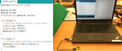
Click here to view program file
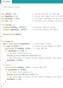
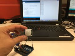
It was a success and I am ready to take a step forward. This time I am going to program using a Aruduino Uno Board to run a PIR (Passive Infrared Sensor). I got the program to run and it works out well with no issues with the Aruduino Uno Board and PIR. I was using the serial monitor to display "Motion detected" when PIR detects something and "Motion ended" when nothing is detect.
Below is a screen shot (on the top) of the program for the PIR and a picture (on the below) of the PIR in work.
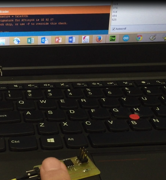
I tried to program using ATtiny and I was faced with problems becasue the limitations of the ATtiny, it does not have the hardware for the softwareserial like Aruduino Uno Board. I tried to program it to work but I failed to do it. My instructor, Steven taught me how to resolve the problem. I really learned a lot from this lesson and I am now having a better understanding with programming. Thanks, Steven...
Below is a screen shot (on the top) of the program for the PIR using ATtiny and a picture (on the below) of the PIR in work using ATtiny.
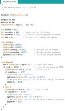
Click on the picture to take a look of the video (PIR in work using ATtiny).
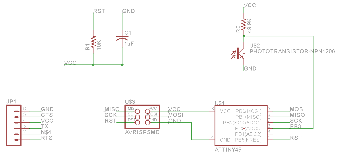
After trying out with the PIR, I am going on to build a phototransistor. First, I used the Eagles Cad to draw out the board using Neil's exaple.
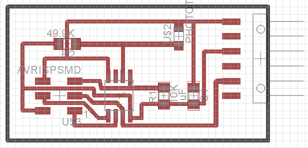
Below is a screen shot of my schematic design and the board outlook of the phototransistor board.
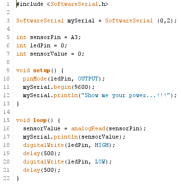
Upon completing the schematic design, I went to cut out the board using LPKF and solder the components on to the board. Last most crucial part is to program the board, I actually went to find Rodney, one of my course mate to help me out. I finally completed writing out the program for the phototransistor board.
Below is the screen shot of the program using Arduino IDE to write out.
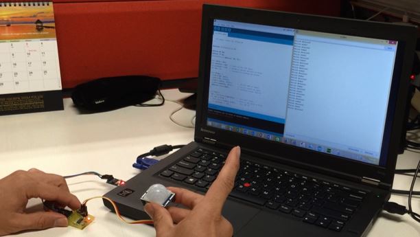
After that I went to try out with the phototransistor and the results was great. It woks pretty well...
Below is a photo of me trying out on the phototransistor board.
Click on the picture to take a look of the video of the test on the phototransistor.
 .
.