13week//

This week I was working on EMBEDDED NETWORKING AND COMMUNICATIONS.
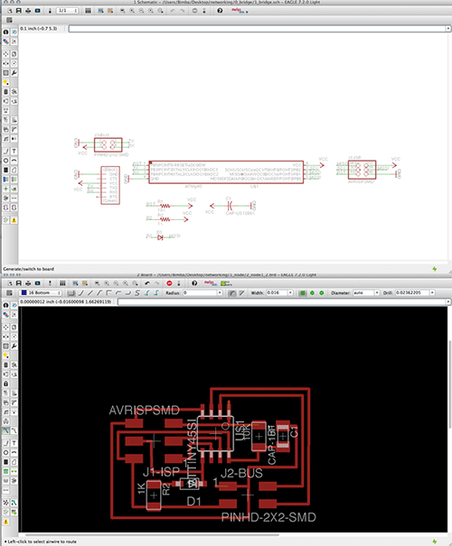
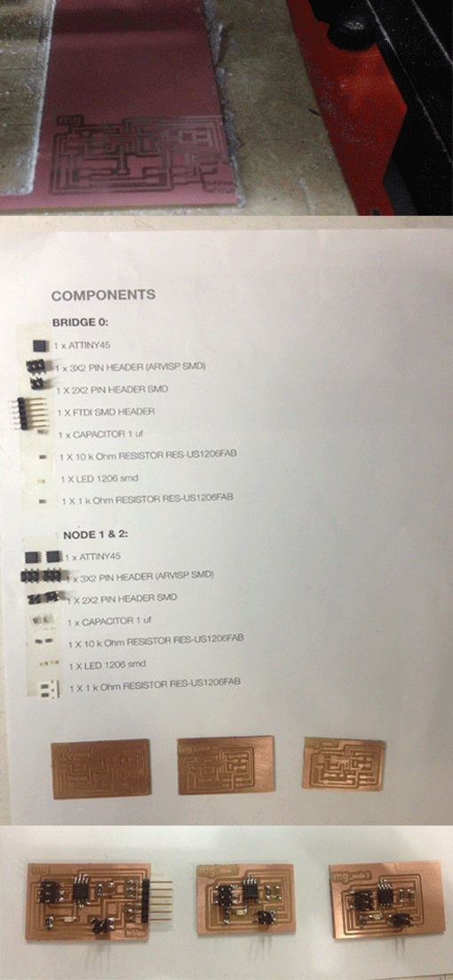
I've worked in make a network with several boards together in the form of a serial bus.
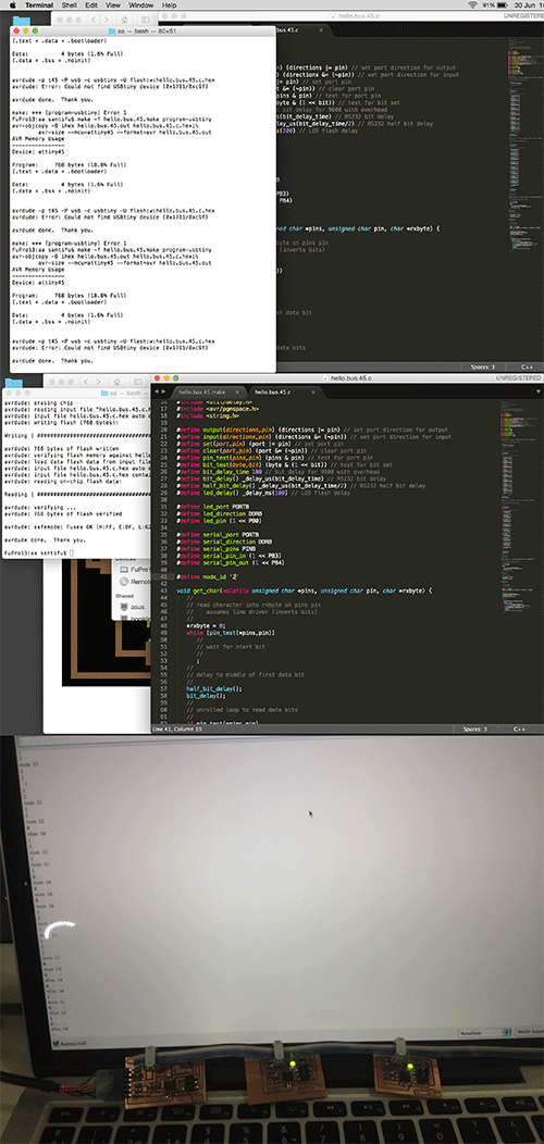
A bridge board connected to my computer with a FTDI cable and two node boards connected with the bridge board to makes a sequence of blinks with the leds.

//Design the schematics and board on Eagle

• I've designed the networking boards on Eagle.

//COMPONENTS:
BRIDGE// Attiny 45, Pin HD 2x3, Pin HD 2x2, 1 FTDI SMD Header, 1 capacitor of 1uf, 1 Resistor of 10K, 1 Resistors of 1K and one GREEN LED 1206 SMD.
Schematics and Board.
NODES 1 and 2 (for each one)// Attiny 45, Pin HD 2x3, Pin HD 2x2, 1 capacitor of 1uf, 1 Resistor of 10K, 1 Resistors of 1K and one GREEN LED 1206 SMD.
Node 1 and 2 Schematics and Boards.

// Milling & soldering

• I've exported my board on Eagle as image.
Settings: .png, monochrome and 1000dpi.

• On Photoshop I've added 0,8mm outside to the board designs.
INTERIOR:
Bridge, Node 1 and Node 2.
TRACES:
Bridge, Node 1 and Node 2.

• I prepared the components as I use and I started to solder the Bridge board and then the Nodes.

• Now the three boards are ready to program it!

//Program the microcontroller

• I've programmed first with my ISP the Bridge.
Then I connected the Bridge and the Node 1 and 2 with the cable that I've made.

• On the C CODE I've defined this parameters of the code:
node_id 0: for node1
node_id 1: for for node2

• My Node 2 board didn't work so I checked the conections with the multimeter and resold the 2 legs of a component that looked no to be attach.

• Now my board are working: LEDS comunicate and blinks!