11week//
This week I was working on Output device to a microcontroller board and program it to do something.
This week I was working on Output device to a microcontroller board and program it to do something.
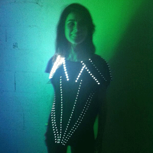
• I have a previous experience putting leds in my T-shirt so I was interested in work on Neil RGB Led to design a board with leds.
//COMPONENTS of the board:
Attiny 45, Pin HD 2x3, Pin HD 3x3, 1 Resistor of 10K, 1 capacitor of 1uf, 1 IC2 of 5V, 2 Resistors of 1K, 1 resistor of 499 and one LED RGB.
After put and connect the components
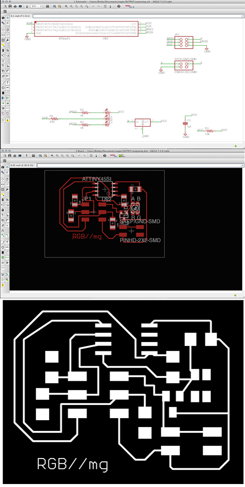
//EAGLE: schematics and board.
• I've exported my board on Eagle as image. Settings: .png, monochrome and 1000dpi.
• On Photoshop I've made the interior and traces (adding 0,8mm outside to your design).
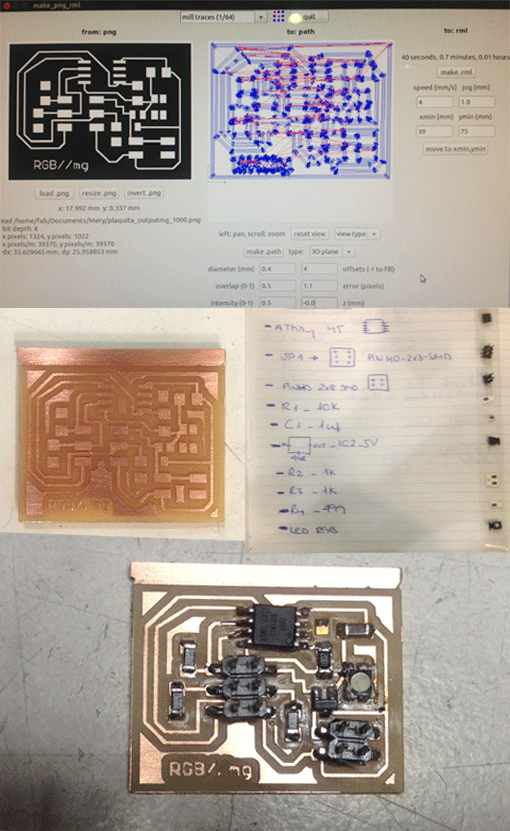
• I used Fab Modules to prepare the files to send to the Modela milling machine with the regular tips for electronics.
• When the board was milled I've started to solder the components from bigger to smaller checking the board on Eagle to understand where the components must be.
• Before to start to program it I checked with the multimeter if all the conections work and... is it!
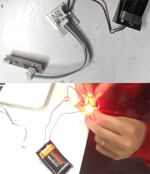
• To program my RGB board, I’ve connected it to my ISP board and to an external power supplier.
• I’ve learned to use external power source with my output board. I've put a 9V battery to give voltage to my board. Pay attention how to connect the positive and negative pole correctly to don't burn the board!
• I’ve put the C Code and the Make file in the same folder.
• On Terminal, I’ve opened this folder and I’ve written:
sudo make -f hello.RGB.45.make program--usbtiny
This command generate two files: hello.RGB.45.out and hello.RGB.45.hex and program it directly
• Now my board is working: BlinksBlinks!