pamela chami
  • home
  • about me
  • project
  • assignments

week06

Electronics design

This week assignment is to redesign the echo hello-world board and add a button and a LED. It was better then I thought it was going to be. The electronics production week was a lot of help in the milling and the soledring part.

Smiley face Smiley face

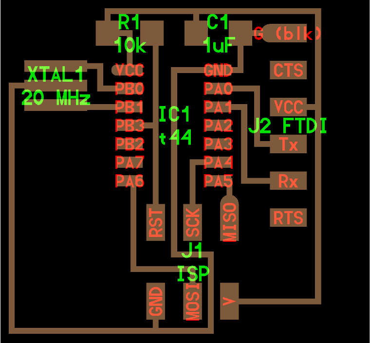
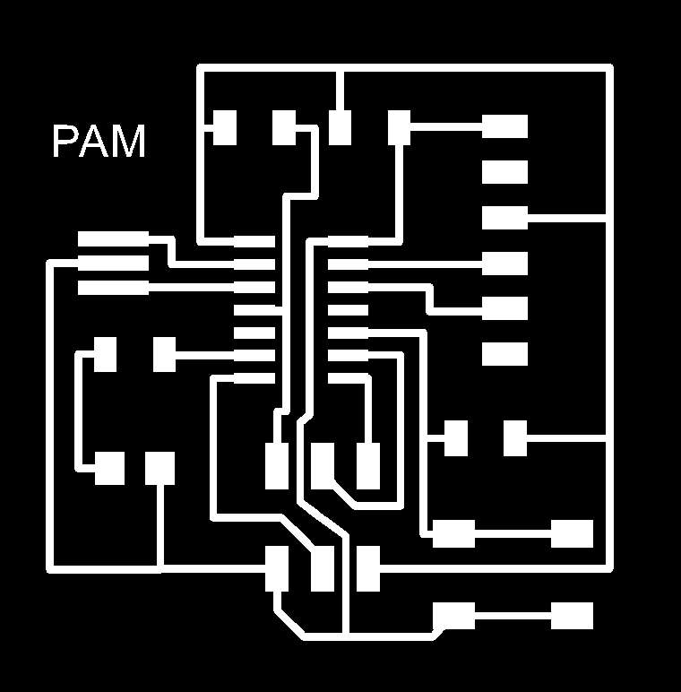
Re-draw the echo hello-world board + add button and LED:

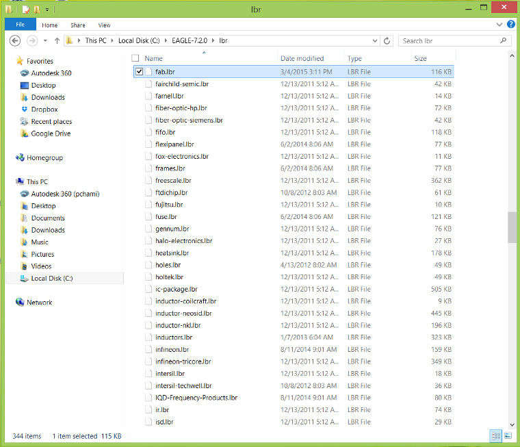
First, I started by downloading Eagle, a PCB design software,and the Fab-libraries, a library of components to use for the hello-world board provided by the academy, to start to re-draw the board. The zip file of the fab libraries should be copied into the local disc on the computer for windows, in my case: Local Disk (C:) - Eagle - lbr.

Smiley face

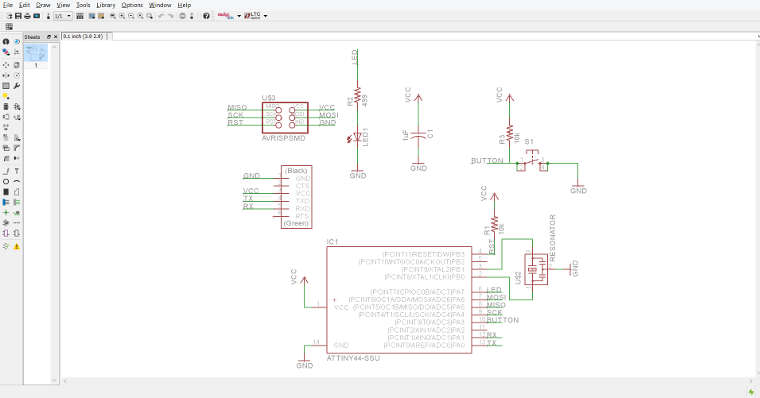
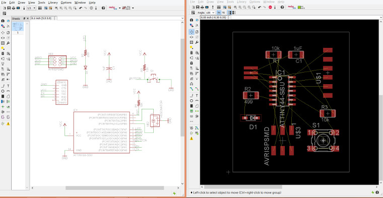
Once Eagle was downloaded and the libraries were set, I have created a new project with the Schematics and the board view which always work both in parralel. Then I have added all the components that I need to use from fab library in the schematic view.

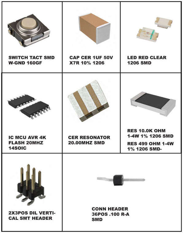
Here is the list of all the components needed for the hello-world board:
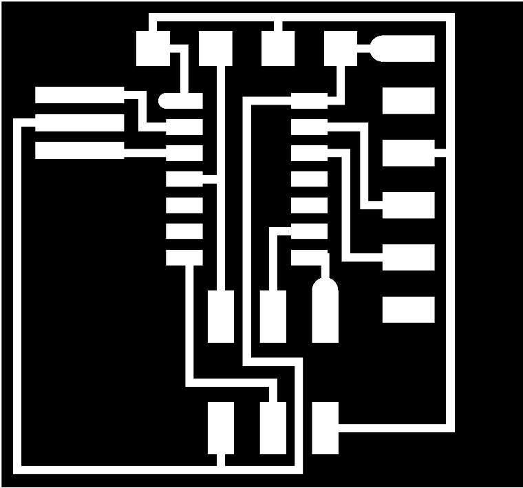
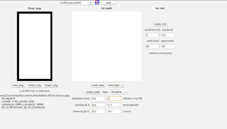
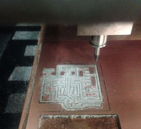
Smiley face

Steps to follow for the schematic and board view:
  • Add all the components
  • Wire the circuit by creacting connections between the components
  • Name and label
  • Verify the design using the ERC (Electrical Rules Check) and fix all the errors
  • Smiley face

    On the board view, yellow traces will be displayed to assist in the routing phase. After routing all the traces and connecting all the components together in the right order, here is the circuit I have designed:
  • orientation of the components are important to understand the connection between them and have an easy trace and clear design
  • keep some space and distance from a component to another (it will also help for the soldering later). In this case it is important to leave a little space the FTDI header connection.
  • verify the position and connection using DRC
  • Smiley face

    Smiley face

    Smiley face

    To export the image to the milling machine:
  • Turn off all layers and keep only the layer 'top' on
  • Save it as .png
  • Raise the resolution (dpi) between 500 to 1000
  • Check the monochrome option to have the image in white and black
  • Smiley face Smiley face

    Milling:

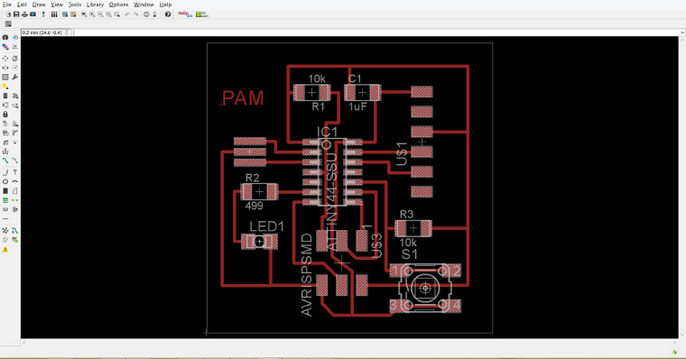
    For the milling part using the modela machine, once the images has been exported as .png and the copper boards are perfectly glue and in place, we need to follow the same steps as the previous milling we did couple of weeks ago:

  • 1- Make input: images.png to output: RolandMDX-20.rml
  • First thing to do to is click on View and set the origin X and Y and the Z point by lowering the bit so it touches slighty the copper plate.
  • 2- Load .png
  • 3- Fix the preset of the traces
  • 4- Make path
  • 5- Make rml
  • 6- Send it and begin milling
  • Smiley face

    Smiley face

    Soldering

    The soldering part went good and faster then the first time ! I listed first all my components on a sheet of paper to be sure that I got them all and then started the soldering !!!

    Smiley face

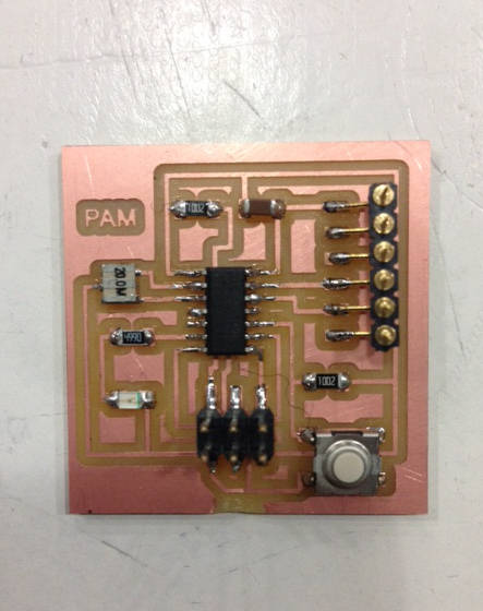
    Here are some recommended tutorials that hepled me a lot with Eagle:

  • Tutorial 1 schematic design
  • Tutorial 2 Printed Circuit Board Layout
  • Download the file here : HelloBoard - eagle file

    Fabacademy.org | Copyright © pamelachami | Design by pch