Week 10Assignment: measure something: add a sensor to a microcontroller board that you've designed and read it
Programs/Machines:
Lessons Learned: When having issues with sensor readings, always first examine your soldering connections, odds are traces are crossing paths.
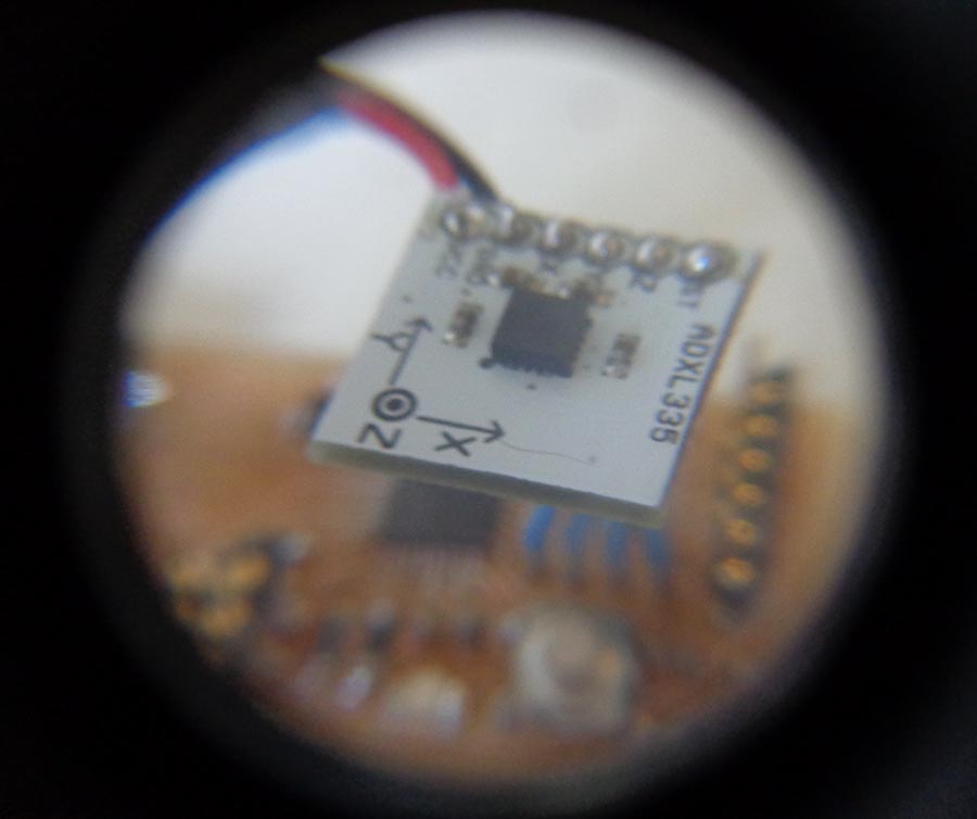
For this week, I wanted to work with accelerometers as I'll be using them for my final project. As for the mircoprocessor board, I wanted to jump in and build an Arduino from scratch and then work in some breakout boards to make the inputs and outputs I'll need a faster and stronger microprocessor for my final project and this board is quite robust so I decided to try it out.
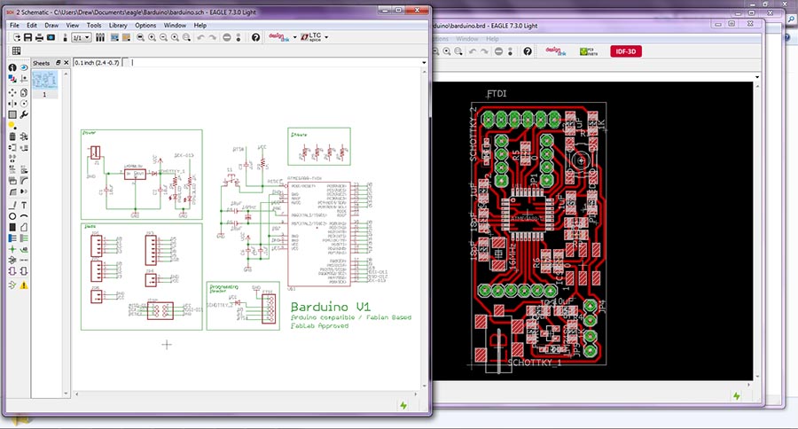
I've never used an accelerometer before but i found this handy tutorial (http://www.dimensionengineering.com/info/accelerometers) that explains the details of them. The accelerometer runs on 3.3v and the Barduino has a 5V regulator on board so I integrated a logic convertor onto an input and output pin in the Barduino board. I downloaded the schematic and board files of the Barduino, found here:(http://fabacademy.org/archives/content/projects/barduino/index.html) There I made a few modification: added two resistors for a logic converter, removed a few unnecessary digital pinouts to make space, and added a small logo.
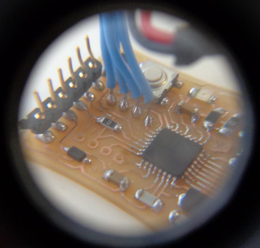
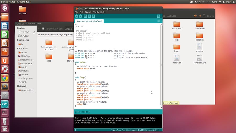
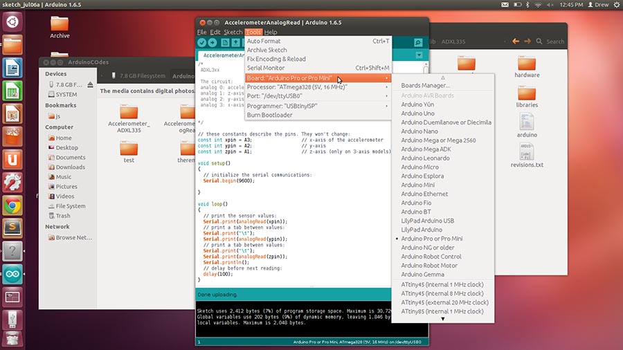
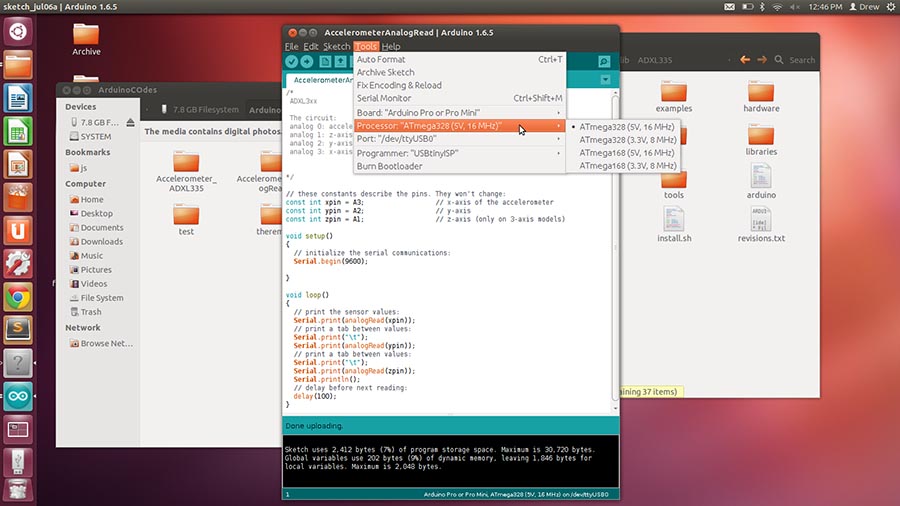
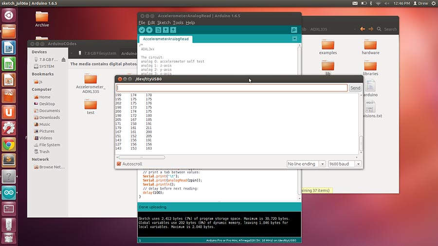
The board was milled successfully and the components were soldered on. To write the bootloader I used the IDE from Arduino. Under Tools>Board>Arduino pro or pro mini (5V, 16 MHz, w/Atmega 328). Everything programmed successfully and a test blink sketch uploaded fine. Finally, I wired the accelerometer to the board and tested it using a simple analogRead() function in the code.
Downloads