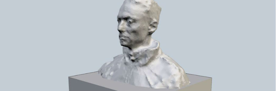
3D model
Comes from a 3D model scanned
File to Shopbot
G-code

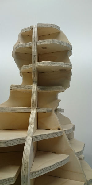
Assembly
Digital carpenter
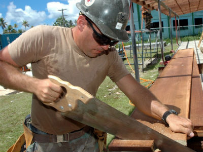
Many things that can make a maker, are available from a few years ago
: 3D scanning, open electronics , 3D printing etc.
But some possibilities offered by digital production revolutionizes
the traditional way as some materials are worked. Wood is an example. With
computer-controlled machining wood can get very good results in a short
time.
From a 3D design, make it in parts that could be assembled using wood and a Shopbot.
Go to www.123dapp.com and download 123D Make software.
Install and open.
Create an account with your email and a password.
Open Autodesk 123D Make
If you have previous file from 123D catch or 123D Sculpt (like me, please
visit my 3D scanning assignment on week 5), you will find all these files
available to work with. On the upper left corner, click and select "Open".
You have some examples available on "Open examples shapes".
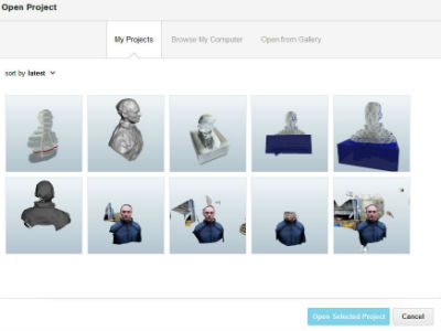
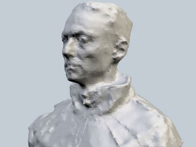
From your gallery, select one of the 3D models. I have chosen my own 3D model from the 3D scanning assignment week.
I have used half sheet of plywood 1220x1220x12mm. Just in case, I measure
it and it was 13,2mm!!
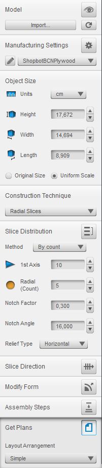
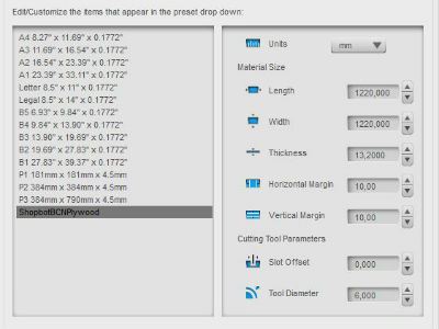
On the left side there is a menu bar, let's set everything:
1.- On Manufacturing settings, click on the pencil button and set material
Name:"ShopbotBCNPlywood". You can put your own name.
Length: 1220mm
Width:1220mm
Thickness: 13.2mm
Horizontal margin: 10mm
Vertical margin: 10mm
Cutting tool parameters:
Slot offset: 0mm
Tool diameter: 6mm
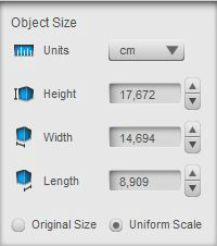
2.- Resize the object.
The object is scalable. I made it as bigger as I could
with the plywood size.
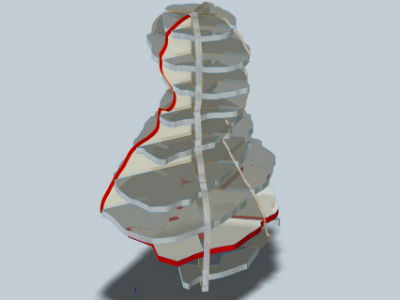
3.- Choose the construction Technique
There are some techniques to choose:
Stacked slices
Interlocked Slices
Curve Radial Slices
Folder Panels
3D Slices
I have choosen Radial Slices
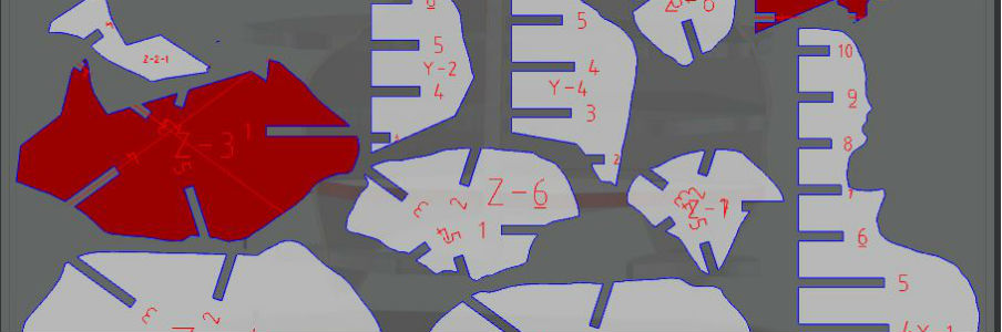
4.- Get Plans and save it in EPS, PDF or DXF.
Download final plans .dxf
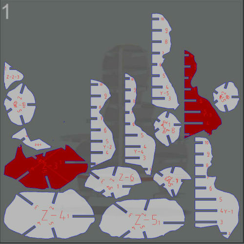
Here it is the plans. I have tried to make it bigger, but it doesn't fit
to the plywood.
Download .dxf plans
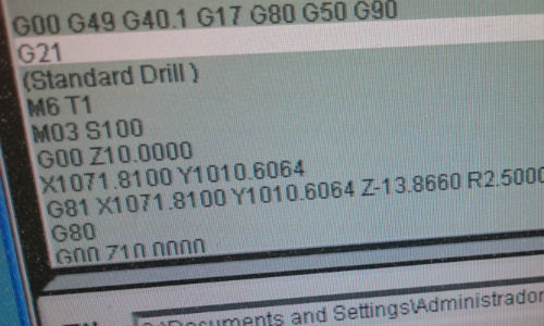
Santi made the g-code generation. At FabLab BCN there are just two computers that can generate it, so it worth to be generated by instructors.
Acording to wikipedia:
G-code (also RS-274), which has many variants, is the common name for
the most widely used numerical control (NC) programming language. It is
used mainly in computer-aided manufacturing for controlling automated machine
tools. G-code is sometimes called G programming language.

ShopBot takes time to finish, most of the times more than 4 hours. Many people, at the same time trying to use them. ;-)
Long size is X axis, short size is Y axis and vertical movement is Z axis.
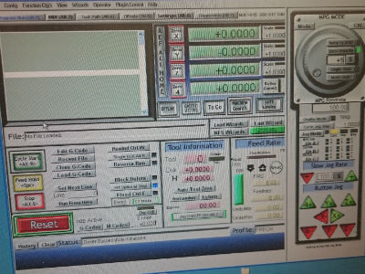
Set at ShopBot software the (0,0,0) at the left button corner of the plywood.
Click on each axis to set it to 0
Load G-Code
Just in case: move up 5 cm the tool and make a simulation. The ShopBot
will do movements without touch the wood. If everything is ok, set the
Z axis again to 0.
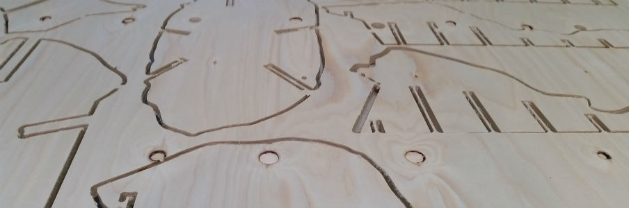
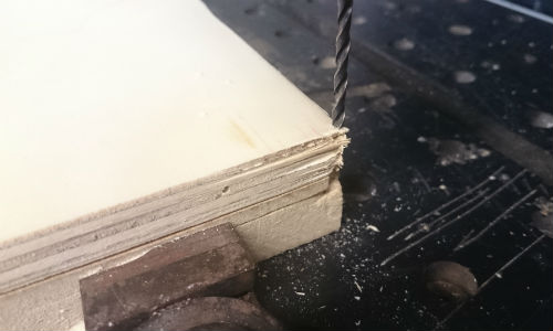
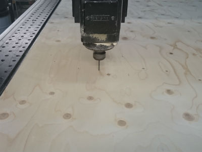
Start operating the Shopbot. First making the drills to screw (3mm tool), introduce screw in order to keep in place the piece of wood and after the cut (6mm tool). The tool is changed manually.
Drills for screws with 3mm tool
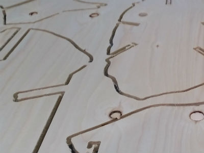
Cut with 6mm tool
After the cut, take out all the screws, move the piece of wood over a
big table, take out all pieces and assemble it.
Here it is!