Outside, a simple Dam
Inside, a piezoelectric sensor
Electronic Dam
For tecnical improvement

Hided Technology
No diferences
Inside, a piezoelectric sensor
For tecnical improvement
No diferences
As a climber, I have always wanted to know what force is supporting each dam.
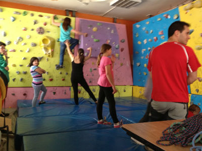
Anyone who has practiced climbing for a while, knows that the technique enables complex movements with less force applied. If you could know what force is supporting each dam, on hands and feet that we support, we could correct a poor distribution of the supports.
In many sports it has managed to successfully introduce technology to
improve technique and performance. We can see that there are force platforms
to analyze the tread on athletes, heart rate monitors which are able to
analyze live heart rate, gas analyzers for athlete's physiology, insoles
for athletic shoes, etc.
In the case of climbing, it would be great to have the feedback pressure
patterns and the distribution thereof. This would allow us to understand
what they are doing champions.
Therefore, one of the ideas of Final Project of the Fab Academy is creating
a Climbing Dam which give the feedback of the pressure is receiving.
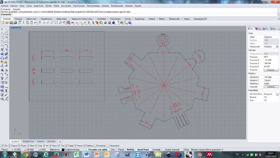
Climbing dam designed with Rhino.
Just for fun, of course. I decided to make all "inside" layers and parts
different. Obviosly, it is not necessary to make all the sizes differents,
and a different assamble joint for every slide, I did it just for fun.
I love puzzles, so these are apportunities for play for a while.
Then, think about how to assamble them (easy way, but just 1 possibility).
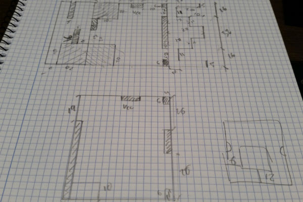
Brainstorming...
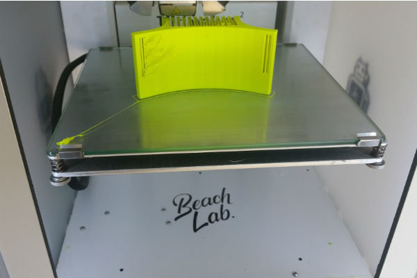
At Beach Lab (Fab Lab Sitges), there is the Full Spectrum Laser 5th gen.
It need the file in format ".svg", so I've designed all parts with Inkscape
and export them to svg or pdf. For engrave, I have used 100% speed and
40% of power. For cut I have used 20% of speed, 100% power.
After some tries, I realized that as much dark is the color, much heat
gets the acrilic, so less power is needed. In my case I was using black
acrilic.
I have used some CAD software this Fab Academy, I would like to try another
one. Sketchup is my option for this design.
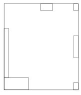
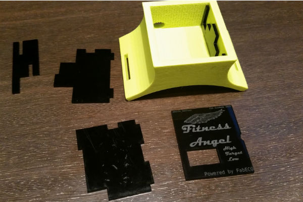
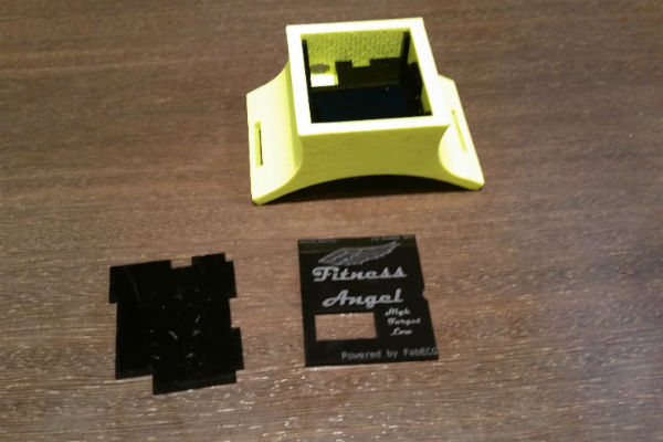
Here are all needs listed:
- Room for battery
- Room for 3 PCB
- Open window for ECG cables.
- Window for visual result.
- Have to fit to shoulder.
- Modular
Let's Start to use Sketchup.
From Sketchup you can export many formats. In this case I have use: ".dae".
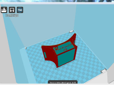
Then another open software "Cura" prepare the file for the 3D printer.
You can see the settings for the first iteration:
Nozzle size: 0.4mm
Initial layer thickness: 0.3mm
Initial layer line width: 100%
Cut off object bottom: 0mm
Dual extrusion overlap:0.15mm
Travel speed:80mm/s
Bottom layer speed: 20mm/s
Infill speed: 50mm/s
Top/bottom speed:20mm/s
Outer shell speed: 30mm/s
Inner shell speed: 60mm/s
Minimal layer time: 5sec
Enable cooling fan: yes
Total time according to software: 4h 26min. (Real time: 4h)
Material used: 4.76m, 38gr
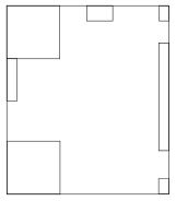
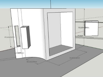
Sketchup is very intuitive and easy to use.
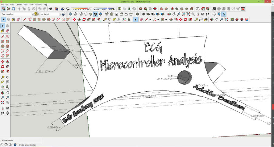
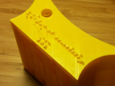
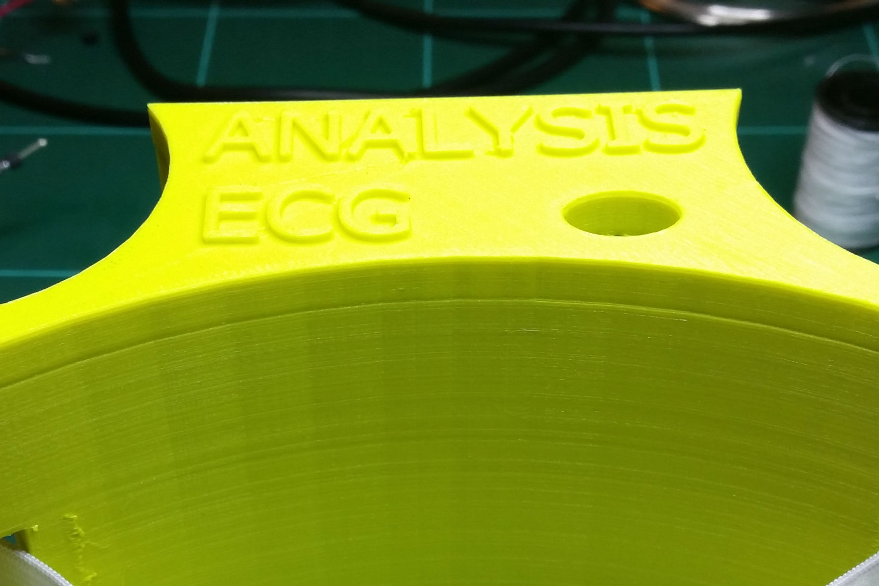
This is my first design. The battery makes me the minimun size. I wish
to write on the top all the minimum information (letters have 0.36mm).
Download the 1st sketchup file
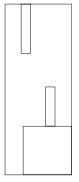
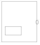
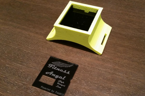
Here it is the first iteration case. As you can see, letters are too thin,
next iteration letters need to be thicker.
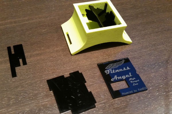
Battery fits perfectly, but it's needed more room for cables 9.23mm is not enough. The upper window for cables have to be wider.
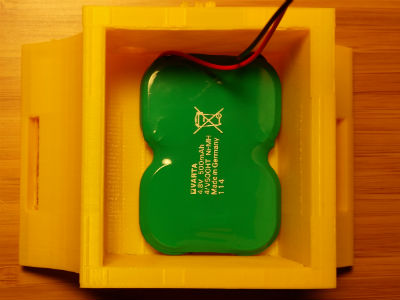
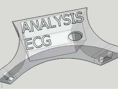
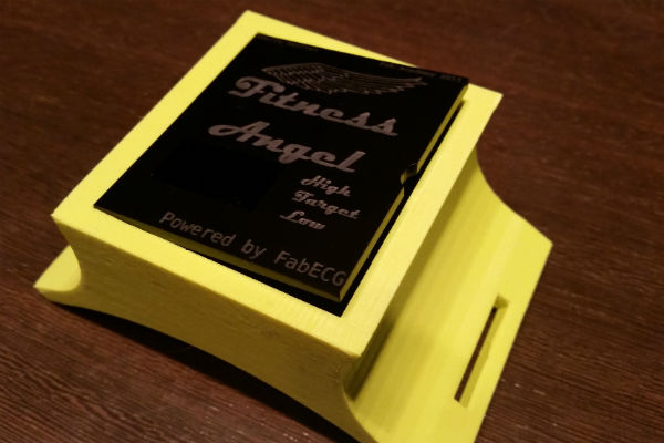
New letters thickness : 1.32mm
Window for cables: 13,8mm
Download the final iteration file zip
(sketchup, dae and gcode)
Now, letters and upper window are perfect.
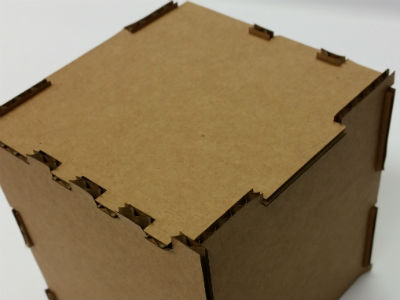
There is just one way to assamble all pieces, that's my puzzle passion!
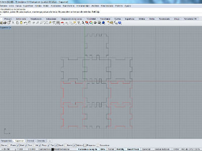
Using Rhino, designing a cube which could be assembled as a puzzle.
One of the most important aspects is the adjustment of the pieces together.
Two layers were done: black layer that will be cut and red layer that
will write without cut. Color red and black will used on laser cutter to
set the tool power.
Download Rhino design with two layers
here.
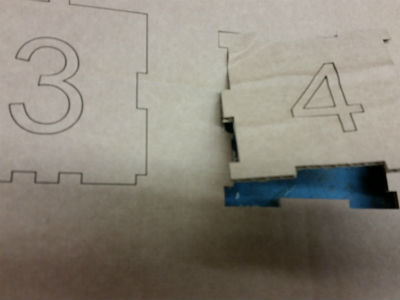
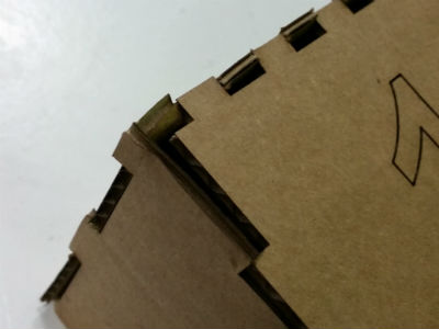
Now, the assembling time. The first time, it doesn't cut or fit the joints well. It was necessary to do three iterations from step 1, redisigning joints size and changing the laser cutter settings.
After my experience with the cube puzzle, I realise that joints have to fit and be enough strong to make a proper assembly. For that reason I started to design all kind of joints for paperboard. The project is in progress.
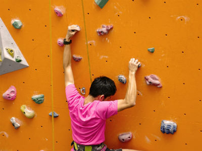
A climbing dam is a hard piece of resin that is used to climb indoor. Usually, a climbing center have a wall full of holes where the dam are screwed.
Open Blender and select with rigth button the initial cube, click on "x"
keyboard to erase it.
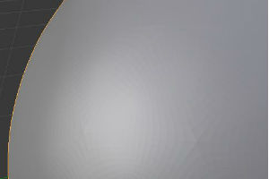
On menu: add/mesh/ico sphere, create a sphere on the center of the screen.
The have no a good "sphere shape" it looks a poligon yet. To improve that,
go to "add ico sphere" and grow up the value to 3 or 4. I did it to 3.
On your right side of the screen, click on "object modifiers", add modifier
and look for "multiresolution". Now click on "subdivide" 4 times for get
a rounded shape.
If you look at the top of the screen you will see "61.442 verts"
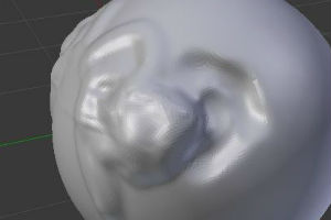
Now, on the button menu, change "object mode" to "Sculpt mode", you will
do crazy changes on the surface adding material with left mouse button,
and substracting material with ctrl+left mouse button. You can change the
size of those adding, changing the radius on the left menu.
Go to edit mode (button menu). Then view/front in order to place the object
in front view. On the button menu change to wireframe. Click on "A" to
deselect everything. Click B, to create a "box selection" and select the
bottom half sphere and delete it with X.
Now on select, verts of the cutted ring. Alt+F, will fill it. Back to
solid mode to see the changes made.
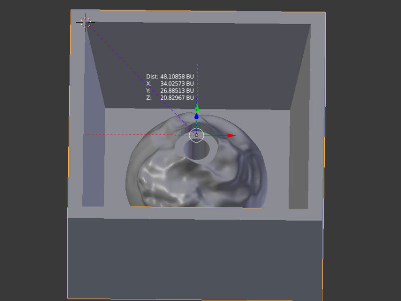
Now, let's make a hole to be able to screw the dam on a wall. On add/mesh/cylinder
make a cylinder. Now it appears a very big cylinder. Put radius to you
screw. Click on "E" you can scale the selected object in any direction.
The screw head is made with extrude and scale options. With boolean
option to substract one from other.
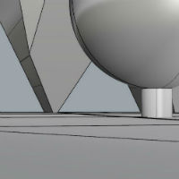
Add a cube, adjust to the dam. with scale and extrude it's easy to make
the cube border. That's final dam. After finish it, and before mill, it
is necessary to check the object size (it is a 3MB Blender file, so it's
to big to upload to my website).
Download CAD files here (3MB)
I've started with Rhino, in order to create a simple and easy figure to
practice the 3D design and print.
The first idea was to create a hollow cube and print something inside
of it. I wish to use the MakerBot 3D printer, but it seems that with this
technology make a hollow cube is almost impossible. Top of the cube needs
some supports.
Then I was thinking how to solve it: One possible solution is to
make a lot of supports inside the cube and try to take them off through
the holes of the cube. Another possible solucion is to make an internal
structure that support the top of the cube. That last solution I tried.
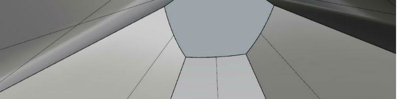
The inside structure is a piramid. We could see the view from the bottom
of the inside of the cube at the the picture .
Download CAD files here
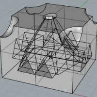
Some subtractions to see the interior and structure.
Inside the cube, just in the middle of the piramid's structure, I created a little ball with an easy breakable support.
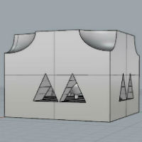
Finally , I took a few bites of the upper corners of the cube to save some material.
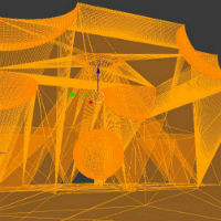
At Blender Software, I make sure that all the normals are well-targeted.
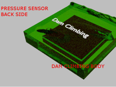
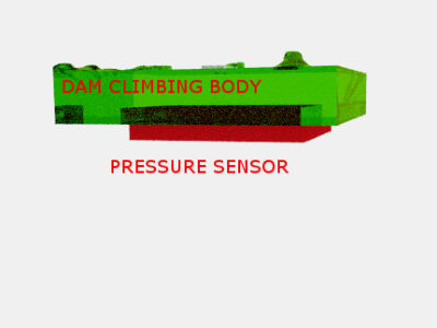
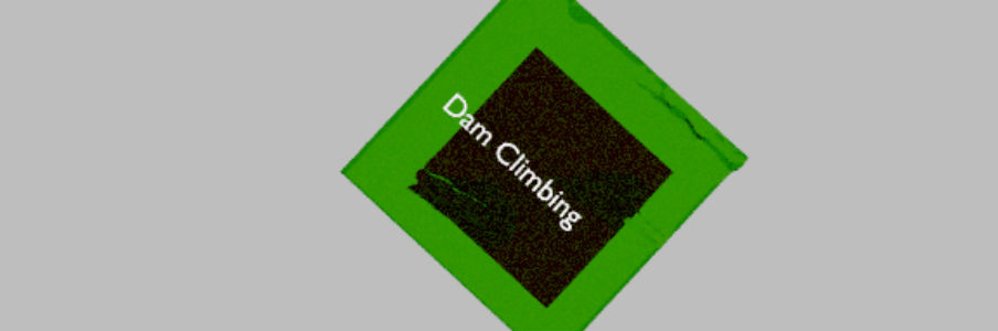
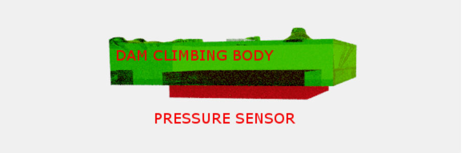
The dam will have two parts: first one comes in contact with climber's
hands and feet. We will call "the dam's body" The second part is the pressure
sensor, could be used a piezoelectric sensor.
I have designed with Rhino, you could have a look of the Rhino files
here.