Sending bits
For my final project, I will need to communicate three PCB. First the
Fab ECG (PCB1) will get the electrocardiogram and will send the analog
signal to a attiny44 (PCB2), which will do a analog to digital convertion
of both input pins and make a substraction.
PCB2 will process the ECG and will send thre states to the 3rd PCB (PCB3)
that is a LED array, wich will show one of the three states.
For this week, I think is more interesting to show here the communication
between PCB1 and PCB2.
Advanced assignment: Get the ECG from Fab ECG, send analog signal to PCB2, PCB2 do ADC and substrantion.
Content (linked):
Assignment:
Communication for ECG detection
In this assignment I will communicate the Fab ECG PCB with Heart Rate
Detector PCB (COM1), then vía Serial Port with Serial Chart Software on
LapTop (COM2), and finally, Heart Rate Detector PCB with Array LED PCB
(COM3). For this assignment I have descrived COM1 and COM2.
To place ourselves in the set of all the interactions and communications
of my final project, I made a video of just over 5 minutes that makes a
mountain view of the electronics.
Fab ECG get the electrical activity from my heart. (INPUT SIGNAL)
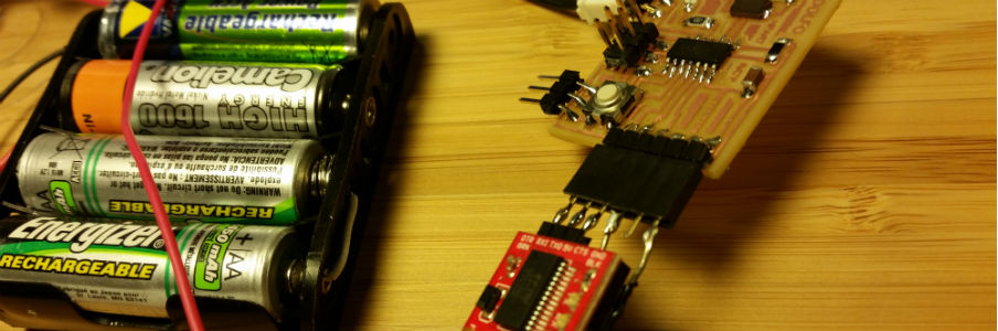
I have made the Fab ECG and it is working. Now I wish to create the PCB2
in order to communicate them and send the electrocardiogram analog
signal.
PCB2 has some design requirements, in order to be useful for the ECG signal
processing.
Although for this week communications assignment is not essential
to know these requirements, I consider interesting to include in the documentation
of this week.
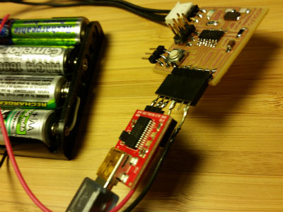
Fab ECG (PCB1) has sent an amplified ECG to PCB2 (Heart Rate Detector PCB)
This seems to be the easiest task and, probably, the first task to do.
If I can know when beat the heart, I could calculate the heart rate, do
a tacogram, work with heart rate variability, and so on.
If I just want to know the Heart Rate, there are many other options to
explore like Fast Fourier Transform of a moving window.
I started studying the Attiny44 microcontroller. I need to check if is
able to carry out the "to do list".
There are many options to try, the microcontroller has to be able to address
them all. About the sampling rate needed for the analysis of the ECG:
According to "Task Force (Standards of measurement, physiological interpretation,
and clinical use)". European Heart Journal (1996) 17, 354-381 on his page
11:
"limited sampling rate induces an error in the HRV spectrum which increases
with frequency, thus affecting more high frequency components"
"The optimal sampling rate range is 250-500 Mz or perhaps even higher"
According to "Errors due to sampling frequency of the electrocardiogram
in spectral analysis of heart rate signals with low variability". Abboud,
S. ; Dept. of Biomed. Eng., Tel Aviv Univ., Israel ; Barnea, O. Computers
in Cardiology 1995. 10-13 Sept. 1995. 461 - 463
"It is concluded that for spectral analysis of the heart rate signal recorded
from patients that are characterized with low heart rate variability, high
sampling rate of the ECG signal is necessary (1 kHz)."
So, sampling rate is very important to analyze ECG. Let's design a circuit
capable of performing a high frequency sampling and then we'll go by programming
the sampling rate as required.
Attiny44 has 10bit and 15,000 samples per second, so this will be enough
sampling rate.
The ECG will come as difference between two pins. The easy way to do this
difference is to input the ECG positive signal in the microcontroller ADC
pin and the ECG negative signal in another microcontroller ADC pin and
substract them.
But the microcontroller has one very interesting option: make a bipolar
differential convertion. On Attiny44 datasheet, page 146 you can
see all the explanations about it.
In my case, I would use pin 6 for ECG positive signal and pin 7 for ECG
negative signal. The MUX5:0 to use would be: 011110.
Following the datasheet explanations, this would be my register
definition:
ADCSRA = (1<<ADEN)// allow analog to digital convertion if it is
1
| (1<<ADPS2) | (1<<ADPS1) | (1<<ADPS0) // Preescale
to 128. The result is 20MHz/128=156250 Hz
ADMUX = ( (0<<REFS1)|(0<<REFS0)|(0<<MUX5)|(1<<MUX4)|(1<<MUX3)|(1<<MUX2)|(1<<MUX1)|(0<<MUX0)//Gain1,
PA6positive, PA7 negative.
Attiny44 has 4K Bytes of In-System Programmable Program Memory Flash. I don't know if this is going to be enough, but probably yes. If after this first iteration I see there are not enough memory, I will change attiny44 for the attiny84 with 8K Bytes.
I need 2 pins for external Clock, 1 pin for feedback LED, 1 Pin for reset,
2 Pins for TX and RX to check with de serial port what is going on into
the microcontroller, 1 pin for button feedback, 4 pins por communications
(ecg in, ecg out). So attiny44 have enough pins to cover all.
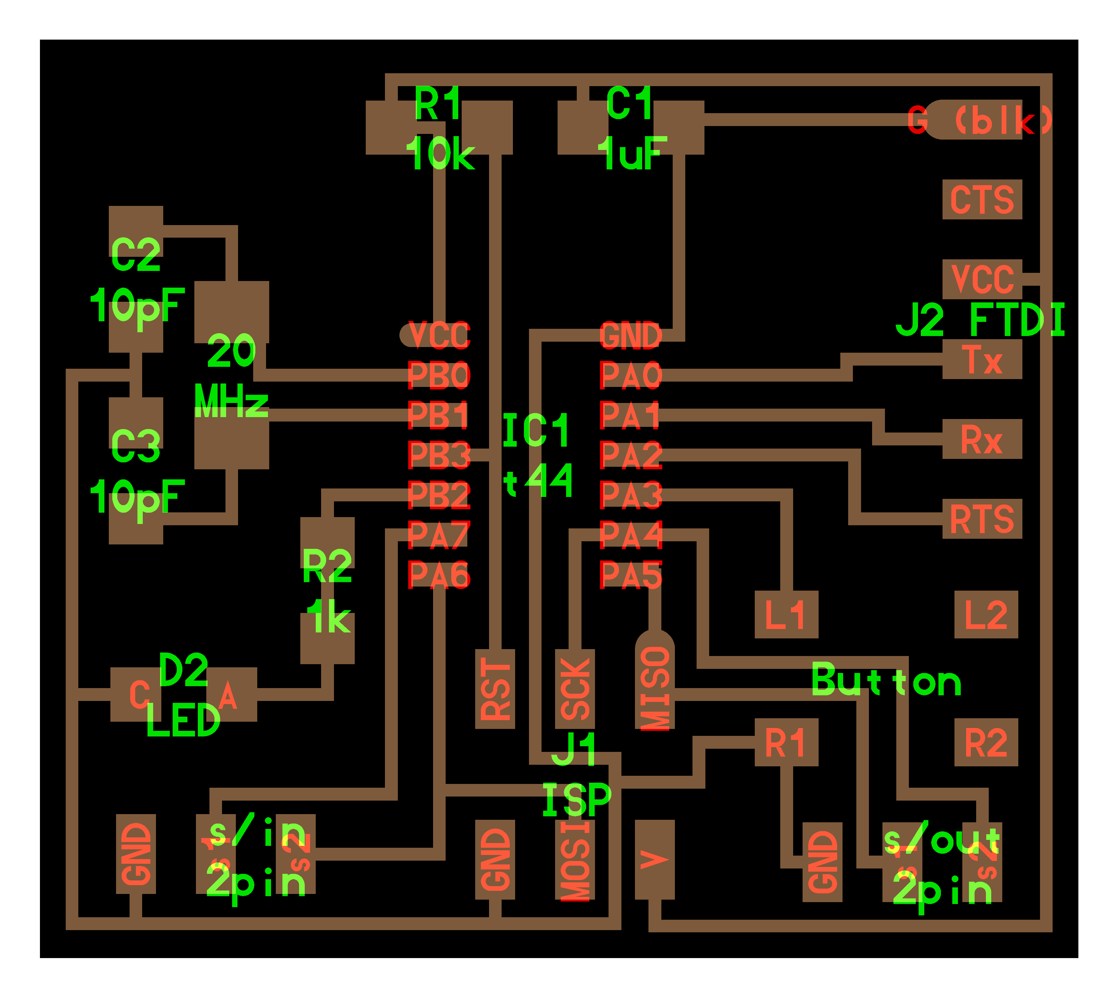
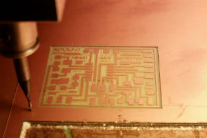
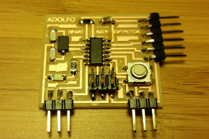
This is the PCB, designed with Kokopelli.
You can
download all files here.
Button and LED are for feedback,
s/in is ECG signal from FabECG,
s/out is to LED array output Board,
R1 is to avoid random reset,
C1 is to avoid jitter AC/DC supply (I will use batteries, but many times,
for test I will use USB 5v supply),
External 20MHz Clock.
In Kokopelli I have created a new class "header_signal_2_pin"
And here it is all the PCB design.
Component List
Modela is a very usefull machine, I really love it. Probably is the most
used machine at any FabLab.
Please, check out on my assigments how to used it, I have explain it on
two assigments.
Soldering and checking all solder with microscope.
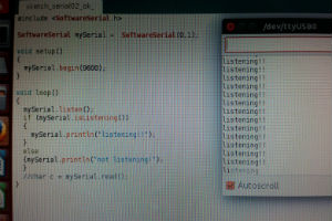
Serial Port is working, microcontroller send the message correctly, but
I can not receive signal from ECG. I have checked Fab ECG with the osciloscope
and the ECG is working fine. Something is wrong on that board.
I should check everything again.
Fab modules, just before sending the path
Yes, I know it will be easy with Arduino, it will be quick to program
but the microcontroller it will work slower and will use more memory.
I know all of that, and for that first iteration I prefer to check, as
quick as possible, if it's able to detect the ECG and try to manipulate
it (detecting de Heart Beat it will be first!).
It doesn't work yet, I can read serial port, but not the ECG.
Two differents power supplies at the same time. At the first stage, the
FabECG was supply with batteries, in this second stage I have connected
the FTDI to read data from the PCB, and (of course) have 5v from USB supply.
After many tries without any positive response of the PCB, I decided to
check one by one all the components... and then I realized...TWO POWER
SUPPLIES!!! Ehem...It could have been worse not to have fed with no power
supply. Lol!
Well, after two days looking for the problem, come back to the project.
Now The FTDI will not use the VCC and GND pins. ;-)
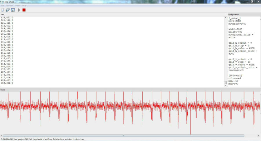
PCB2 (Heart Rate Detector PCB) sent the digital ECG via serial port to my Lap Top (COM2)
Every test, I have to read data with the Serial Monitor, then copy and
paste all the row data, and analyze with Matlab or Excel. Every little
change it takes a while.
I decided to look for a Serial chart. A software to read serial data and
make a chart in real time. This is the the SERIAL CHART. it runs on windows.
The web page were is from: https://code.google.com/p/serialchart/
You will need to check first that you can see data on your serial monitor
on Arduino IDE.
Download Serial Chart
Download Imu (coded for ECG detection)
Go to the download folder, move the zip file anywhere you want.
Extract the files into the folder.
Run the software "SerialChart.exe"
First, let's check if the port is available:
on a windows terminal ( command prompt: open cmd) tape: netstat -an
You will see a list of port and the state.
Control panel/system and security/System/Advanced System Settings/Environment
variables
Inside the "System variables" look for "Path", edit.
Add (add this to the the paths): c:\windows;c:\windows\system32;c:\windows\system32\wbem
put ";" between any path.
OK and get out of all windows, even the command prompt.
Open again the command prompt and try netstat.
Go to device manager/ports (COM &LPT)
Right click on the port you want to change. Click on Properties
Port configuration/advanced options. Change the Port number to a
COM<10
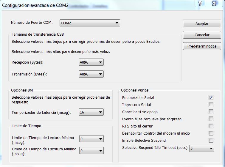
Port=COM2
bauderate=9600 (same than Arduino .ino)
chart settings: width, height and background color
With or without grid. Set where to put the origin and the steps.
Variables. Color, min chart value and max char value.
Data have to come from serial port like that:
data1,data2,data3
Download my setup for Heart Beat Detection
This is the final appearance of serial chart working.
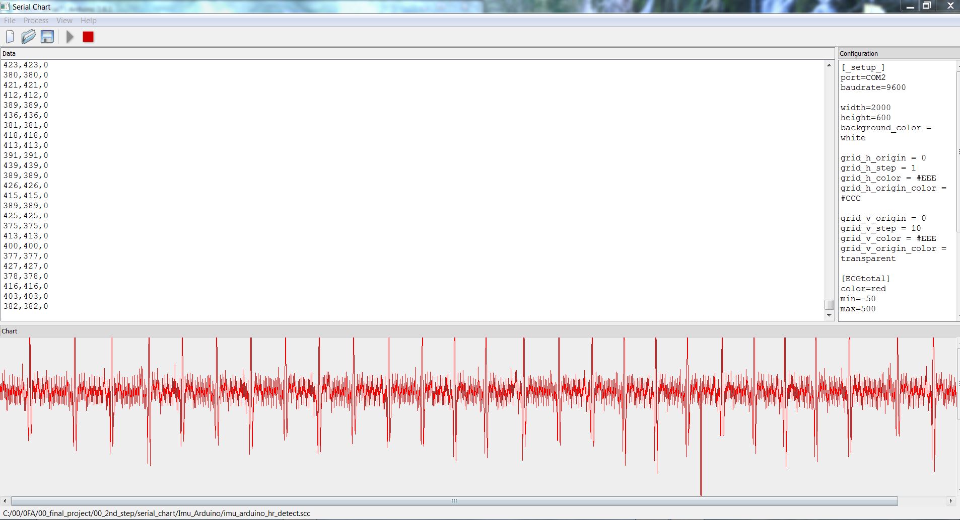
To summarize so far: the electrical activity of the heart is obtained
with Fab ECG, sends the amplified analog ECG (COM1) to PCB2, which is digitized
and make a difference between the two signals, then a list of those three
data are sent via serial port the laptop (COM2).
Download a spreadsheet with an example of all data and a threshold detection of 500. Data from COM2.
In the final project (see the project pages) explains in detail all interactions
and communications between the PCBs.
Arduino sketch:
- Read ECG
- Make ADC from ECG1 and ECG2 signals (positive and negative)
- ECG=ECG1 - EG2
- Send data separated by commas by serial port.
- Detect Heart Beat by Threshold!!
- Blink LED every heart beat.
Donwnload sketch Heart Beat Detection
PCB2 (Heart Rate Detector PCB) send orders to PCB3(Array LED) (COM3).
Visit my final project page for further information.