C o n t a c t F a c e b o o k S k y p e I n s t a g r a m P i n t e r e s t H o m e
07. Computer-controlled Machining
Make something big
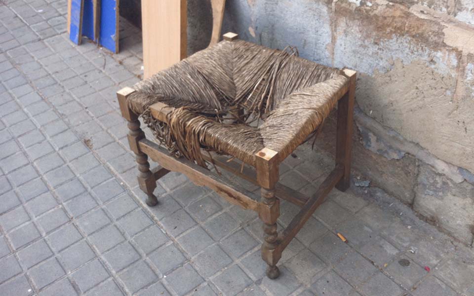
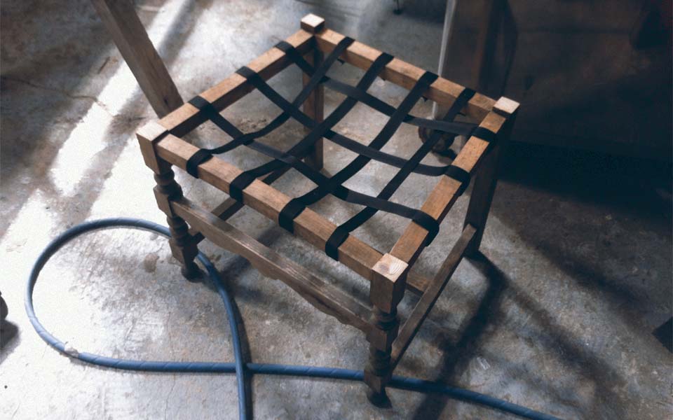
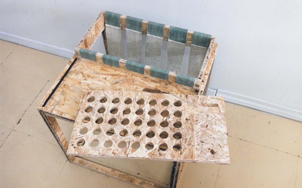
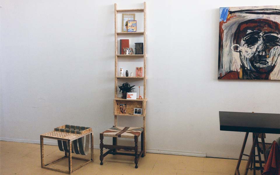
After recently moving into a new place, I was eager to design some furniture for the make it big exercise. The material to be used was a 1250x2500 mm board of 14 mm OSB. Funnily enough, I had found a stool on the streets near where I live and had decided to upcycle it with the material from this week. I decided to design a back to the stool that served as a shelving/display unit. I also was in need of a side table and had decided to design one to fit within whatever material was left of the board.
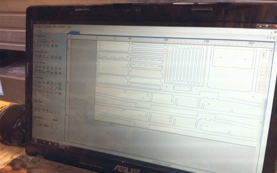
Once I finished the design, I nested all the required drawings within the perimeter of the sheet and prepared the file to cut the pieces in the CNC machine. The design of the furniture pieces was based on a milling bit of 6mm. This is important to the design because there needs to be some corner compensation in order to allow for the bit size to mill corners for good press-fit construction techniques. This file was then exported as a dxf to be sent to the Shopbot.
The dxf file was prepared using the Partworks 3 software and separated into 4 layers for each unique toolpath strategy. The first layer was for the holes for securing the board to the sacrificial layer. The second layer was to be configured for milling pockets. The third layer was for milling the inside pieces and lastly, the fourth layer was dedicated for the outside lines. Once the layers were separated and configured with the appropriate tool bit and toolpath strategy, the OSB board was ready to place onto the machine's sacrificial layer.
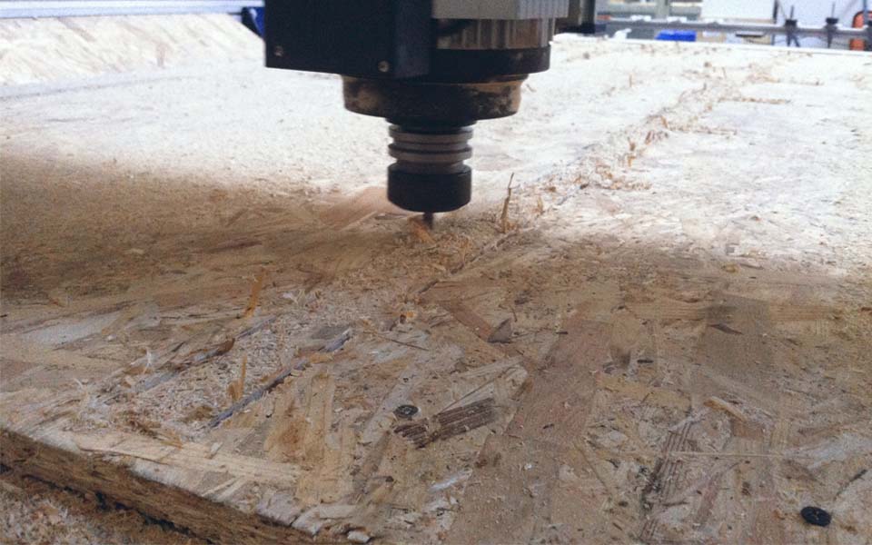
The x, y, and z was then set depending on the location of the corner of the OSB. Then the first layer file was sent to mark the holes. These holes marked where the OSB would be drilled for extra support and were strategically positioned in the most vulnerably weak areas. The holes were drilled and the nest milling files were sent with variable toolpath strategies.
The toolpath settings used were the following:
Cutting depth: 15mm
Tool: 6mm End Mill
Path depth: 5mm
Step over rate: 8000-12000
Feed rate: 40mm
Plug rate: 10mm
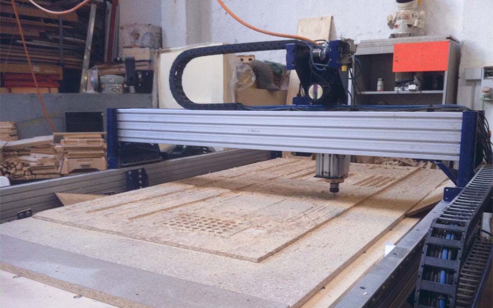
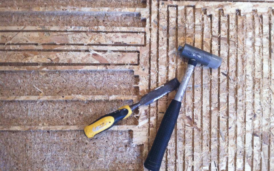
After almost 3 hours, my file was completed and ready to be removed. In order to do so, a chisel and hammer were required in order to chip off the tabs that were placed during file preparation in Partworks. These tabs served to keep pieces from flying off the machine bed and ruining the machine, or possibly the cutting pieces. With the tabs removed, the pieces and board were easily disassembled.
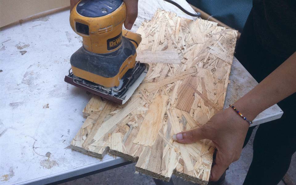
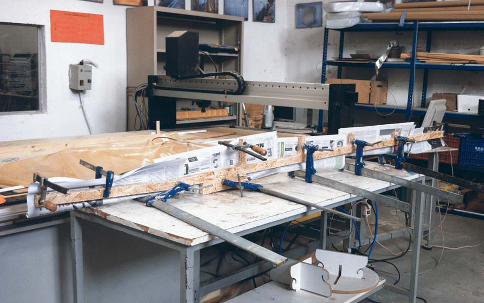
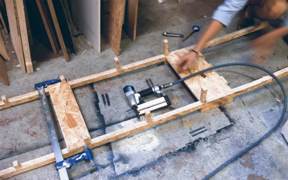
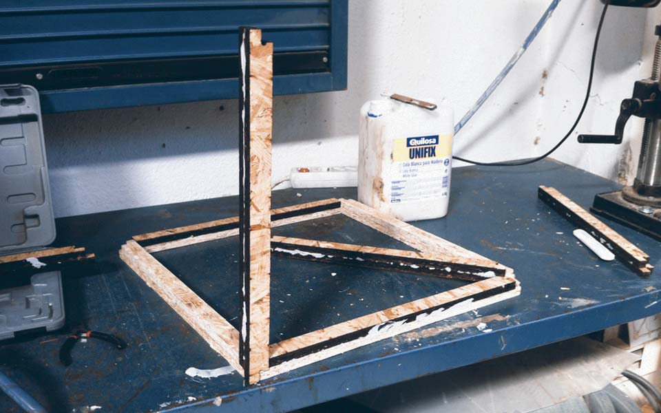
After milling, it became apparent that cuts were not regular and were of poor quality. This is due to the irregular nature of OSB. With a little sanding, these pieces were smoothed down to a more manageable shape. Finally, the pieces were assembled. Because of the lack of structural rigidity in OSB, I decided to double face the surfaces in order to strengthen the notchings in the design. These are the only pieces that were assembled with glue. Otherwise, the structural system relied only on the notching of the wood pieces with each other.
Download the corresponding files here.