C o n t a c t F a c e b o o k S k y p e I n s t a g r a m P i n t e r e s t H o m e
06. Electronics design
Redraw the echo hello-world board, add (at least) a button and LED (with current-limiting resistor), check the design rules, and make it
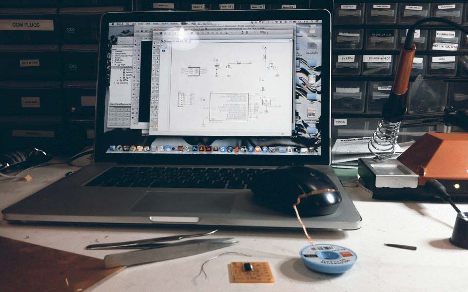
To get started with this week's assignment, I first downloaded and installed the free version of EAGLE. I spent some time reading the Encyclopedia of Electronic Components by Charles Platt and going over tutorials on Sparkfun on electronics and EAGLE before I started to design electronics as a way to better understand the logic behind the process.
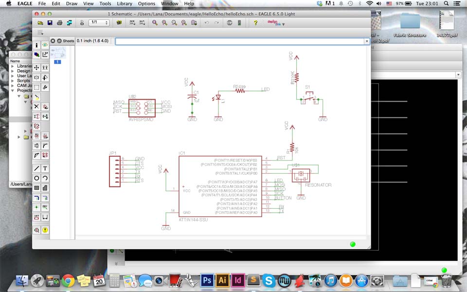
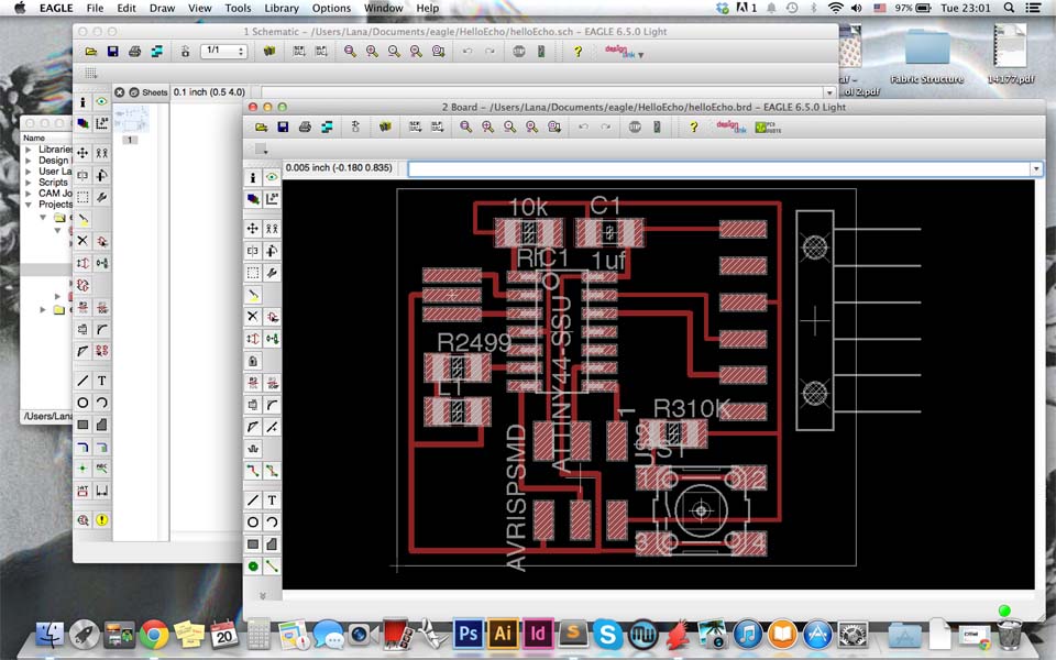
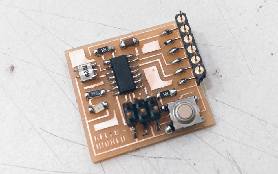
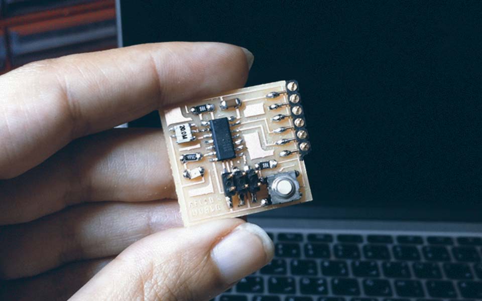
I followed this tutorial but instead of downloading the files available on the website, I started designing my board from scratch. The parts that were added to this board are the ATTINY44A microcontroller, the FTDI header, 6-pin programming header, 20MHz resonator, 2 10K resistors, 499 ohms resistor, an OMERON switch button, and an LED. To connect the components, I named the pins that needed to be connected with the same name. EAGLE recognizes that two pins with the same name are connected. Once done, I switched to board view and began arranging and routing the components on the board.
Getting used to the Eagle interface was quite challenging. Some issues that I needed to get used to were to not close the layout board and not the schematic (or vice versa). Editing one view while the other window is closed will break the link between the two. Another issue was understanding that autoroute is not the way to go about routing the board. Although some people will claim that it is good for making a general layout, I find that it oversimplifies connections and leads to unusable circuit boards. Plus, its not too much of an effort to do it manually.
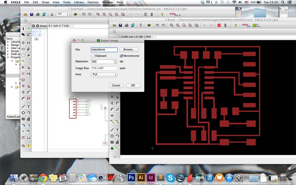
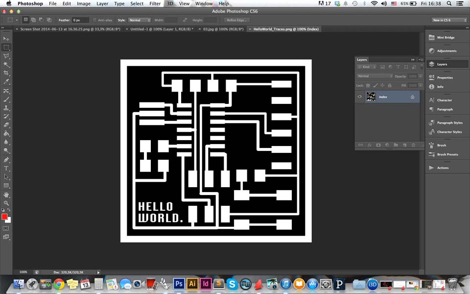
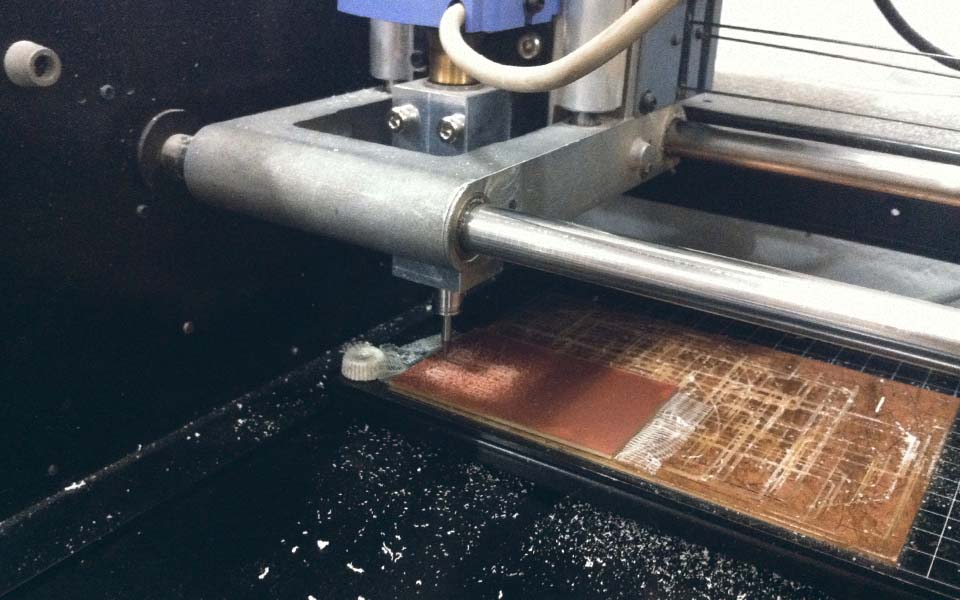
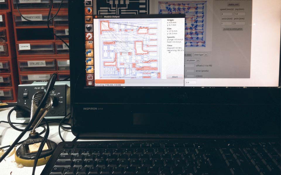
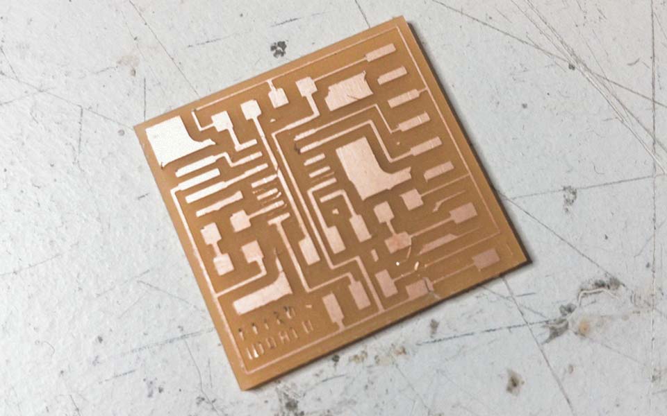
The top layer of the board was then exported as an image file with the settings 500 dpi and monochrome and imported into Photoshop. In Photoshop, the border of the image was increased by 20px on each side and text was added in the corner. Then a trace and an interior file were exported and imported into Fab Modules to be milled on the modela. The boards were then milled following the same format that was previously explained in Week .04. Finally, all the required components were then soldered onto the board.
Download the corresponding files here.