Week 3: Computer-Controlled Cutting
 THIS WEEK´S FILES
This week assignment consisted on making a press-fit construction kit, using the laser cutter.
Testing the laser cutter
Tools
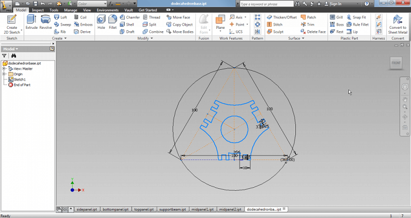
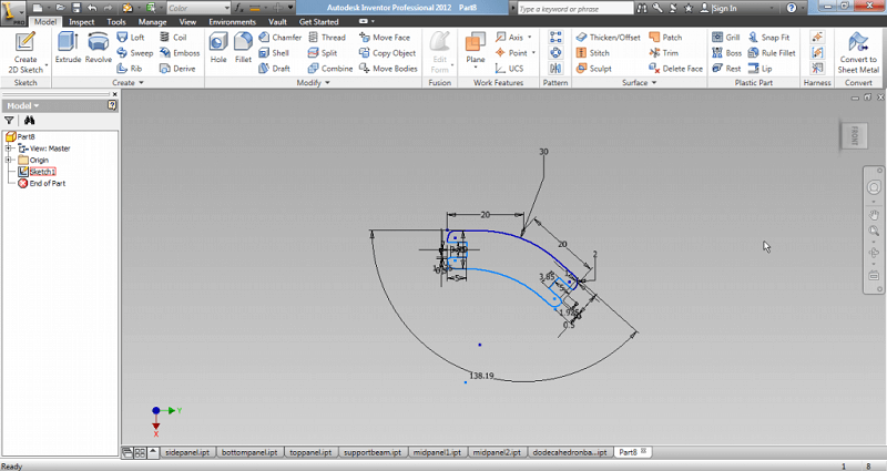
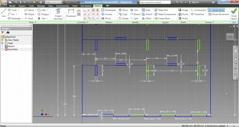
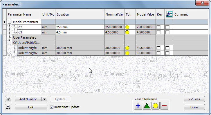
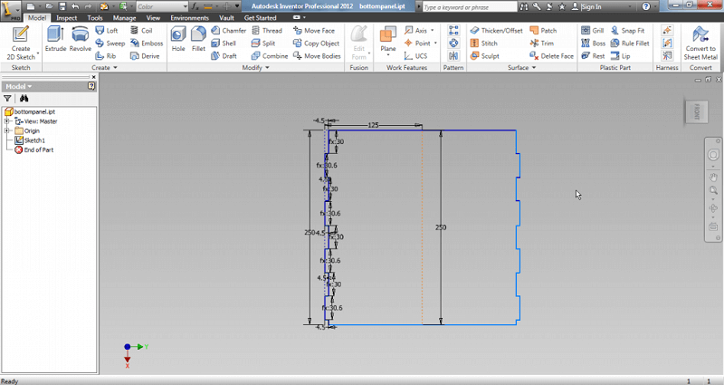
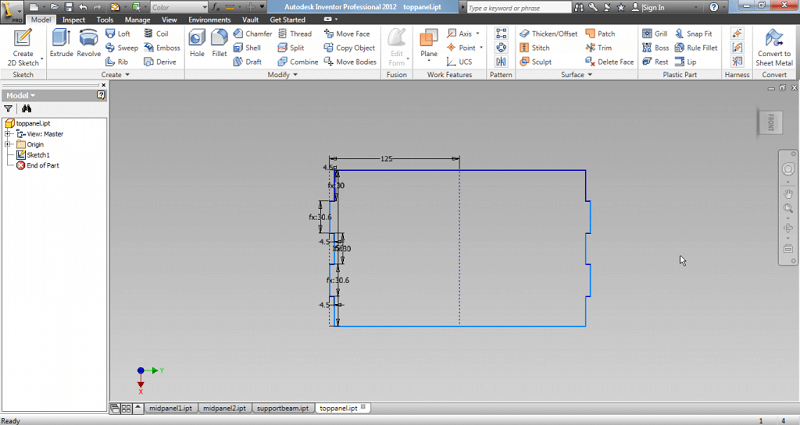
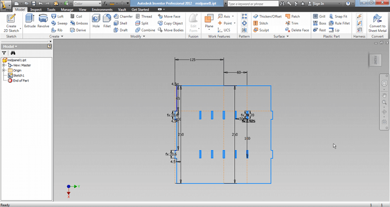
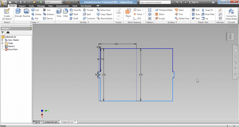
- Autodesk Inventor (Pro 2012): Although it is mainly used for 3d modelling, for this assignment I used it just for making simple 2d sketches. The usefulness lies on the posibility of using parameters for the design, specially for quickly adjusting press-fit indents and holes.
- Rhinoceros: Used to arrange 2d sketches made in Inventor, adding some details, and printing.
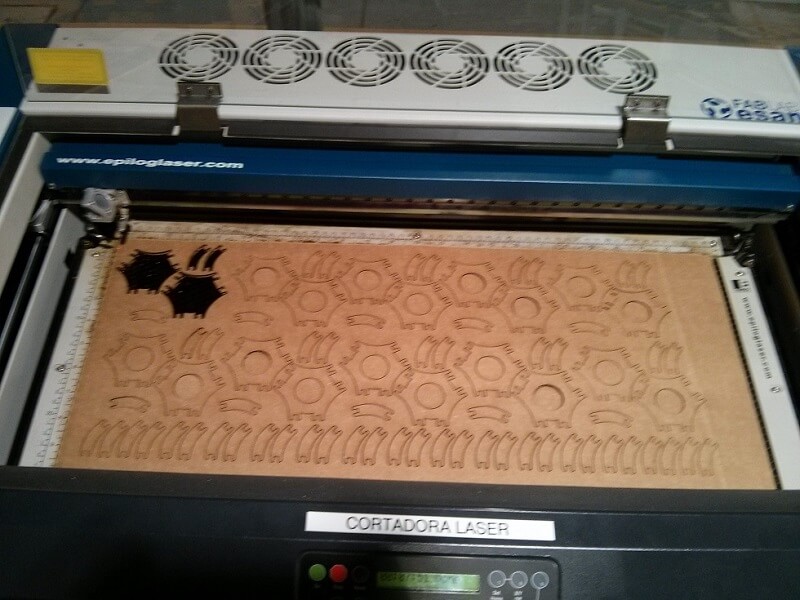
- Epilog Laser Cutter: The laser cutter we have at FabLab ESAN have a working area of 300mm x 600 mm.
- CorelDRAW X7: To create a decent quality (600dpi) image to use in the viyil cutter.
- Roland Vinyl cutter: The vinyl cutter we have at FabLab ESAN, works with fabmodules.
Process
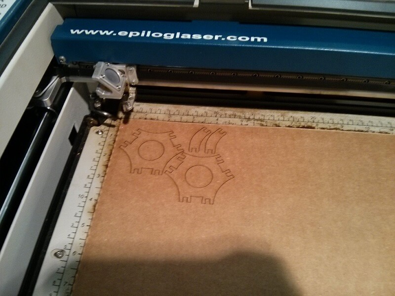
To test how much the laser cut off from the original measures of the digital design, I decided to cut pairs of pieces to test both the width required for correct press-fit of cardboard (the suggested and cheapest material) and length. For width, I measured the width of the cardboard using a caliper, which resulted in around 4.2 mm, so for the first try I tested using from 4.15 mm to 4.4 mm. As for length, I decided to cut a 30 mm hole, and try indents from 29.8 mm to 30.3 mm. I designed on Inventor.
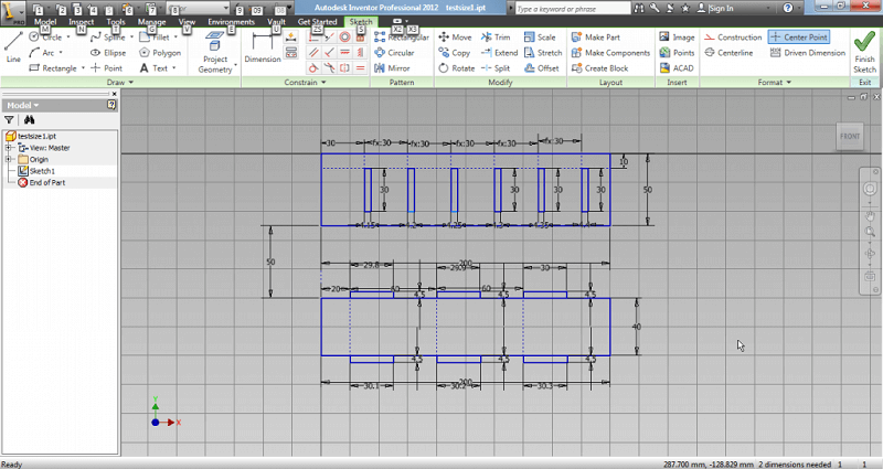
I exported the Inventor sketch to a .DWG file, with 2004 compatibility. This file can be opened in Rhinoceros without problems. A little problem when importing into Rhino is that it considers construction lines made on Inventor as common lines, so one must erase all extra lines before cutting.
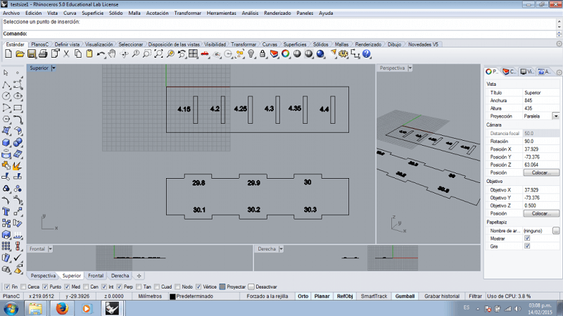
From Rhino I send the design to the cutter (with 40 speed, 100 power, 500 mhz - we already had some recommended parameters for some types of materials). I got my pieces in no time.
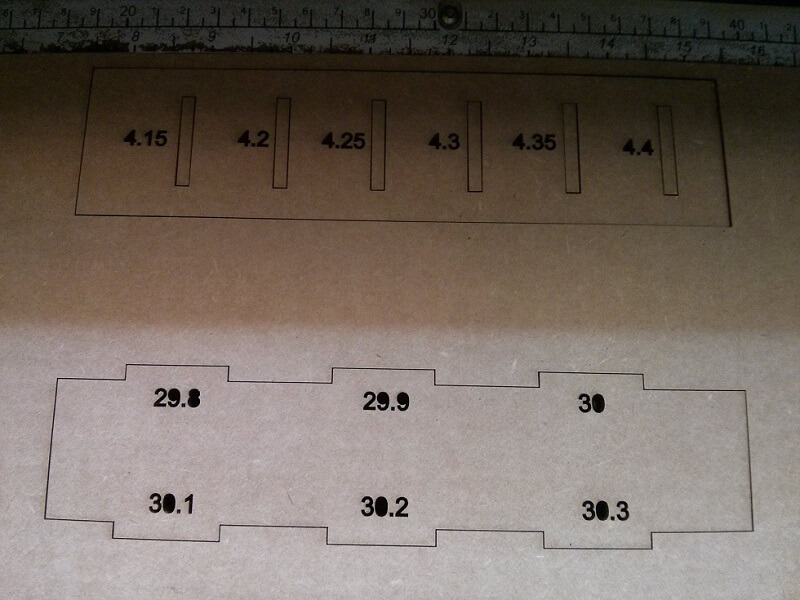
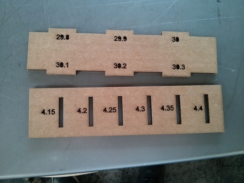
I tested out all the combinations (6x6), but with no satisfying result, as the fitting was not as tight as I desired. I tried again with different measures. In the end, the best results were 3.85 mm for width and +0.6 mm for length. This stage is very important before using the laser cutter, and when using new materials. Taking some minutes to properly calibrate the machine, and in turn our design does pay off later, as the final products are less likely to turn out wrong.
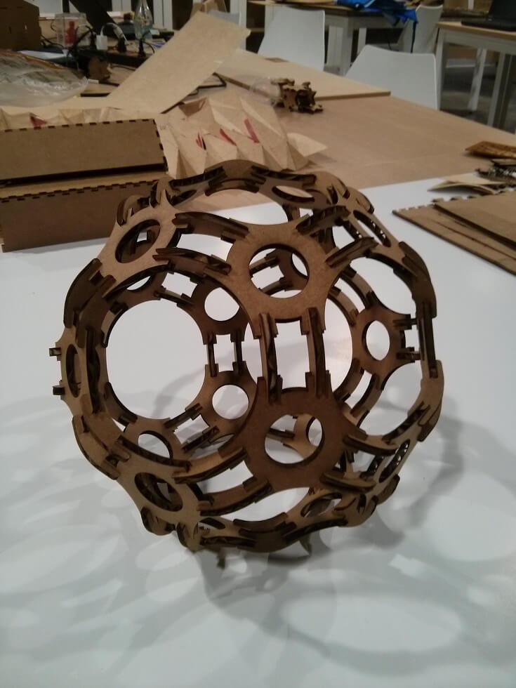
Design #1: Modular design based on a Icosahedron
I decided to make to designs forthe assignments, using different joints.
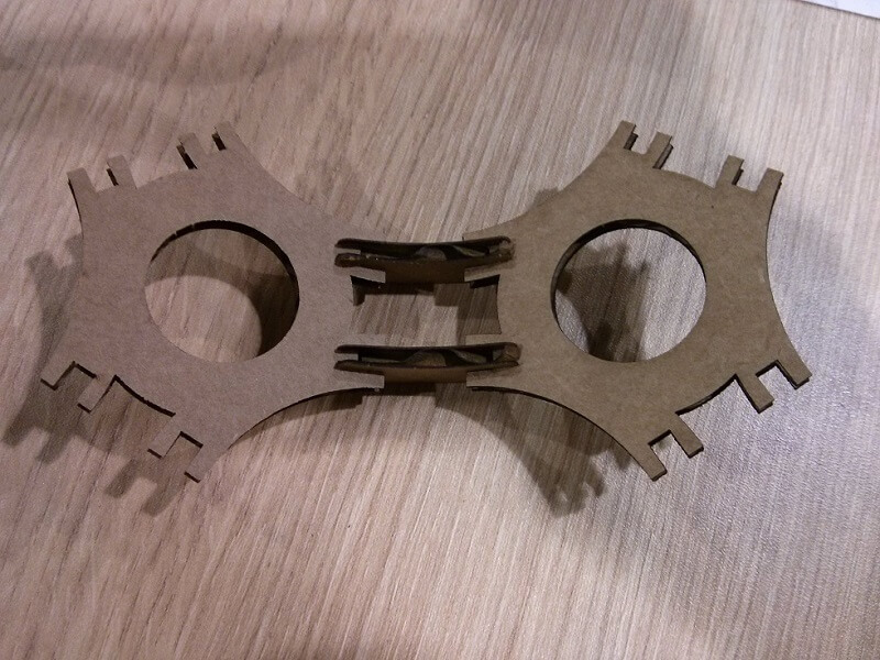
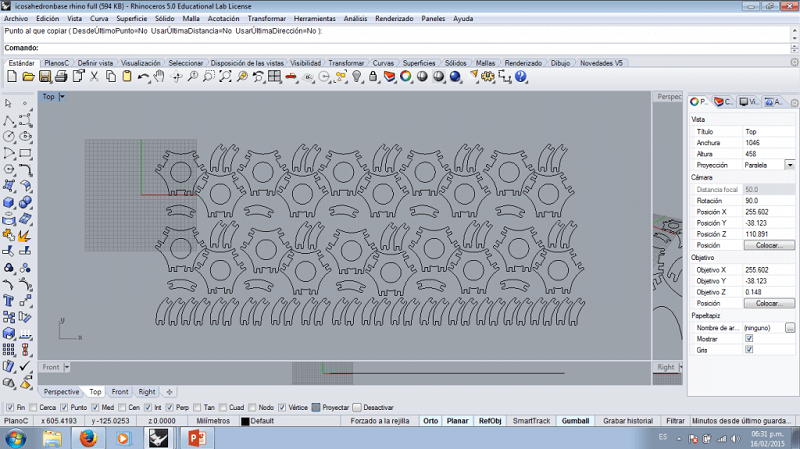
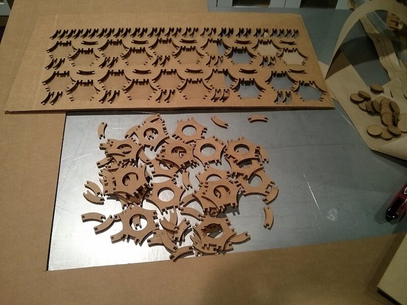
The first one was a simple modular design with just a decorative purpose. The design would use 2 types of pieces: 20 base pieces of a design inscribed in a 10 cm equilateral triangle (one face of the icosahedron) and 60 connector pieces (2 per each of the 30 edges of the icosahedron). For the joints, I use simple press-fit, with indents of 3.85 mm width and 5 mm length (length doesn't really mattered), with slight chamfers of 1 mm.
I export both designs to .DWG and then to Rhino. I arranged a couple of each pieces and cut them to test if the press-fit was good enough. I went out pretty well (as expected).
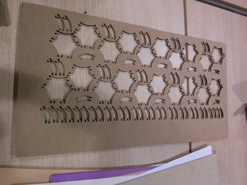
So using Rhino I arranged all the missing pieces needed to complete the deisgn (a total of 80 pieces). I was careful to fit all of them in a simple working space (300mm x 600mm) to use material efficiently. It took around 5 to 7 minutes to cut everything.
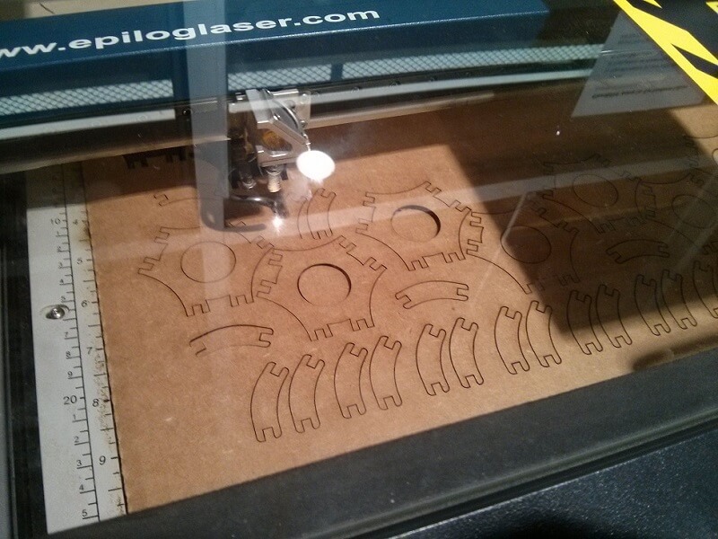
Considering the number and size of the pieces it took some minutes to tear them appart. I had to use a knife to loosen some of them.
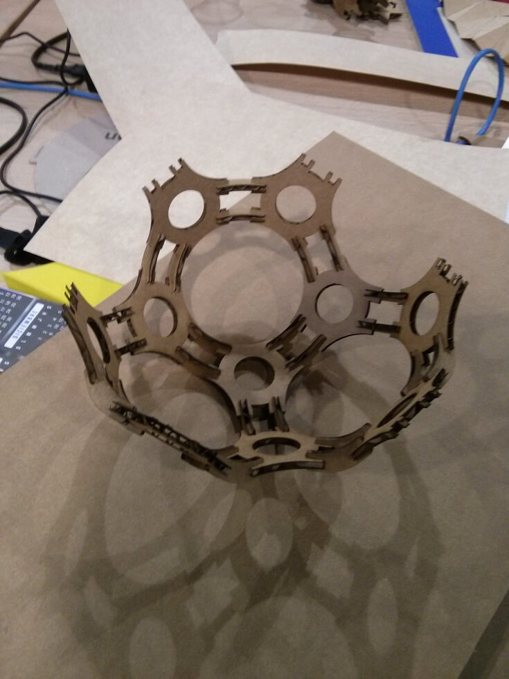
Build time was around 20 minutes. The small indents made it difficult to fit the pieces together, and the chamfers did not help much. The end result was pretty satisfactory, and quite resistant; I toyed around with the ball some time and it is still tightly fitted. I'm considering making it again but with 3mm MDF.
Design #2: Locker Kit
For the second design I decided to make something more functional. I remember that my little sister has been bugging me the last couple of weeks about buying a locker kit (those small shelves for school lockers). I looked in the internet about the design and it turned out that it was not nothing out of this world. Actually, I was so simple that I though about little "improvements", such as making it adjustable.
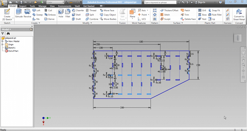
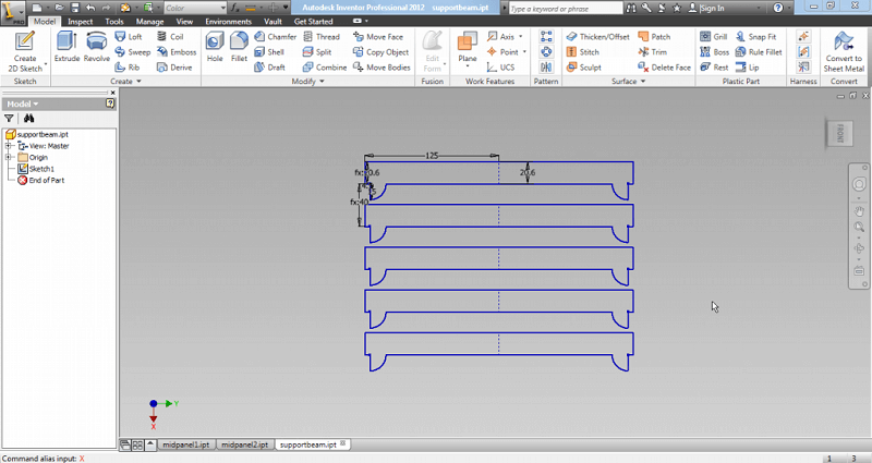
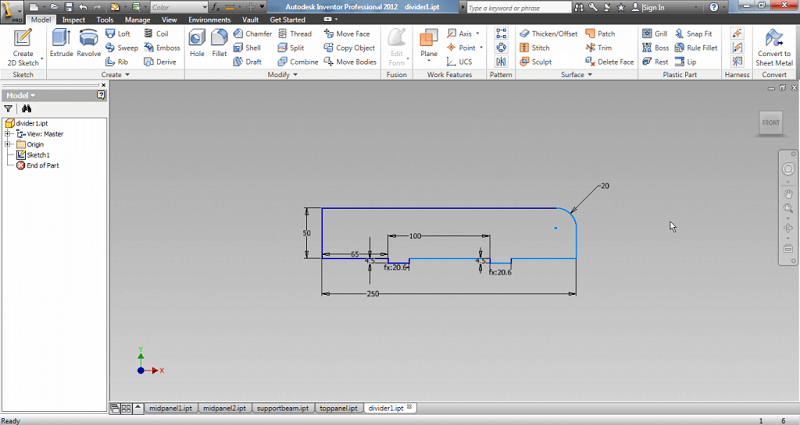
For this design, I set up parameters to quickly adjust my measures. With this, for example, if my material has a different width, I can quickly adjust it and it automatically refreshes in all the components.
I designed a total of 7 different pieces. I use a big scale, but not the real measures as I don't have the exact measures of my sister's locker.
I used the same process as before: export to .DWG, arrange in Rhino, and send to the cutter. I got a total of 13 pieces, and I used 4 pieces of cardboard (300mm x 600mm) because of the large size of the components. In total, about 10 to 15 minutes to cut everything, considering I had to put new cardboard everytime. Build time was around 5 minutes.
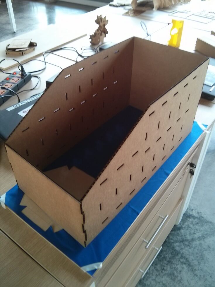
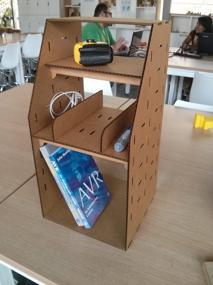
Surprisingly, the final product is much more solid than expected. It could hold some books and random stuff without collapsing. Still, I think that I could try some stronger joints for further iterations.
After having the exact locker measures, I plan to adjust the design, plus cut it in 9 mm MDF (using different joints, according to the new material) to make a functioning shelf.
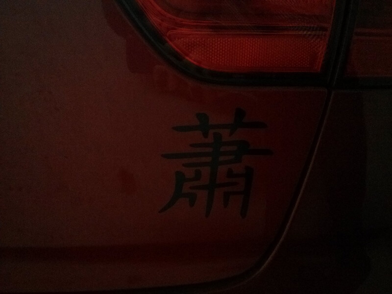
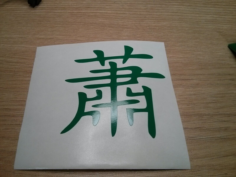
Design #3: Siu Chinese Letter Vinyl
To try the vinyl cutter, I decided to do something quite simple: my surname in chinese. I just downloaded the picture from internet and tweaked it a bit using CorelDRAW to obtain a nice .png at 600dpi. With it, I used fabmodules to create the path for the machine. Fabmodules, both the old and the new one, are very intuitive an easy to use.
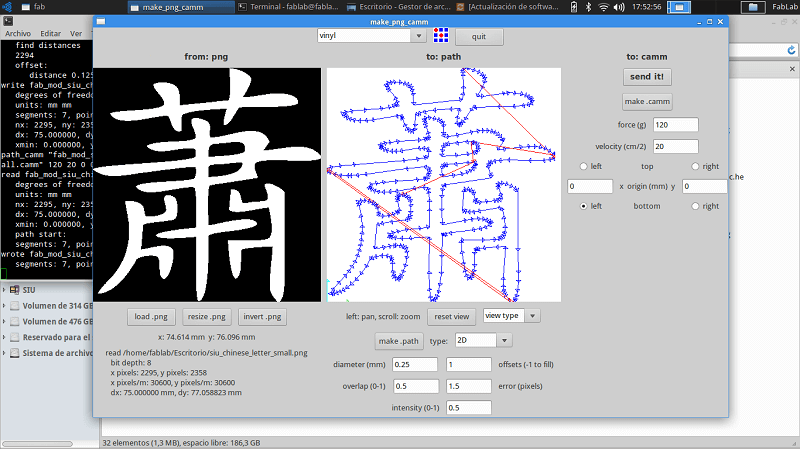
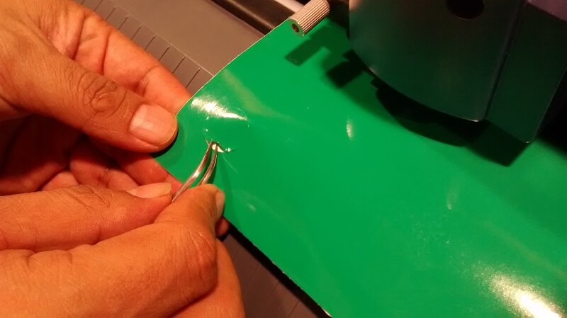
To determine the ideal force and velocity, I did a quick test using the cutter programmed test mode. What it does is to cut a small circle with a square inscribed, using a selected force and velocity. The idea is that if the circle can be removed using tweezers while leaving the square pasted, the settings are good to go. My first try was with force=120 and velocity=20, which wasn´t enought. The second try with force=130 and velocity=20 worked out well.
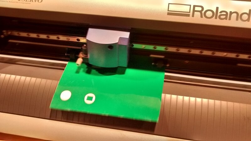
Having the settings defined I just send the path using fabmodules. Cutting took around 10 to 15 seconds. I took out the piece of vinyl and cut out a square with the decal itself.
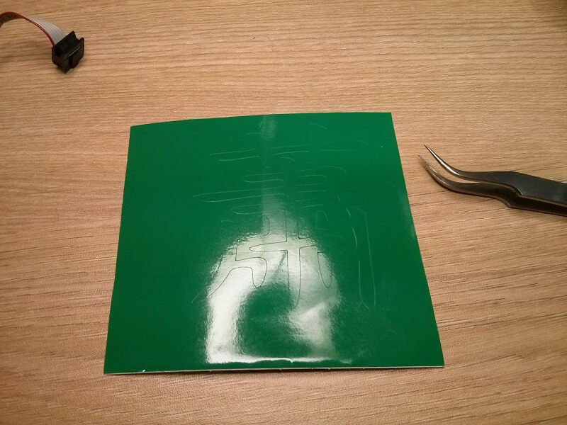
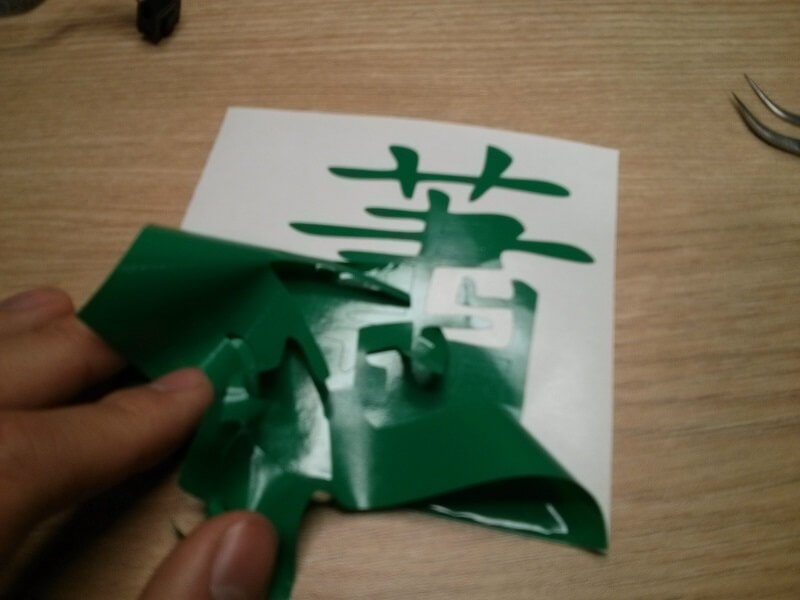
The next step is to carefully remove the excess material, leaving jus the design pasted. The rest can be discarted.
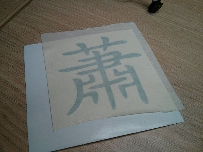
Having the design ready, a piece of transfer tape have to be pasted on top. The transfer tape helps paste the vinyl decal in the final place desired. I cut out a niece square to store the decal for later.
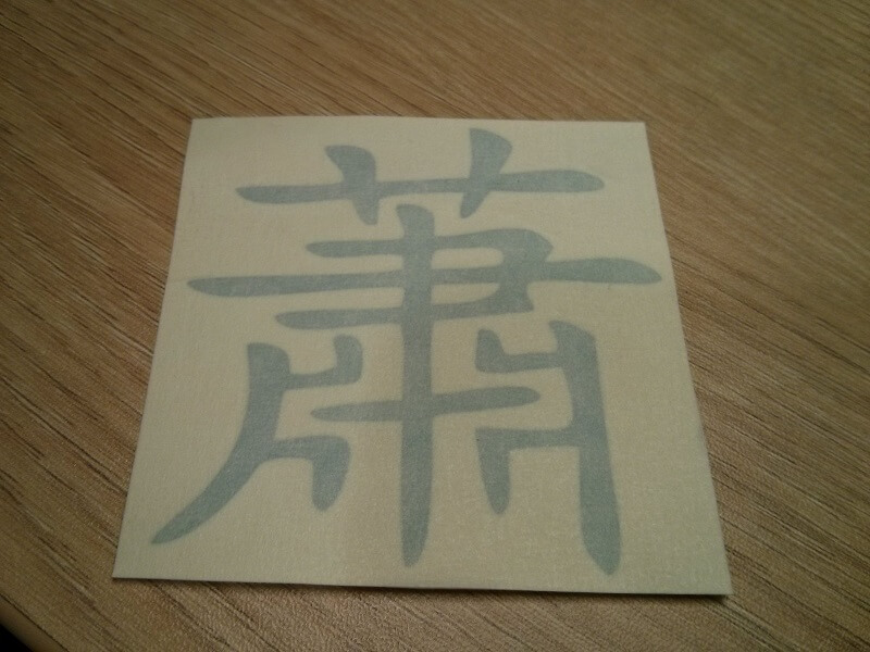
I gave my first try to my sister, so I made another one and pasted it on my car. It is still nicely pasted after washing the car some times.