
Week 13: Output Devices
 THIS WEEK´S FILES
This week assignment was to add an output to a board and program it to do something.
Tools
- Fabmodules: We have it already installed on a laptop at the lab. Used to send the .png traces design to the milling machine.
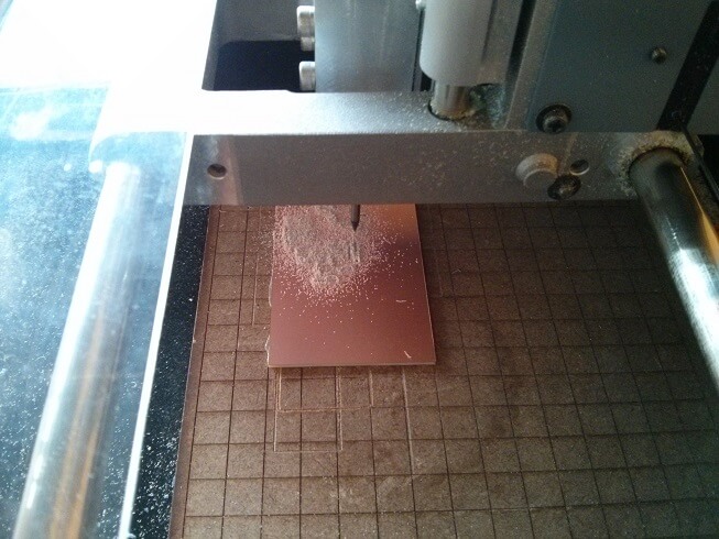
- Roland MDX-20 Milling Machine: To mill and cut the PCB boards.
- Soldering Iron and tin: The basic tools for soldering.
- EagleCAD: To design the new board.
Process
As my final project's main outputs are 2 DC motors (for more torque), I decided to make a board that can control 2 motors. The board would control just the turning direction, not the speed, as for the project the speed is not a great concern. Also, I decided not to use a microcontroller on this board, just make it read data from another processor (either my Pi 2 or a Fabduino).
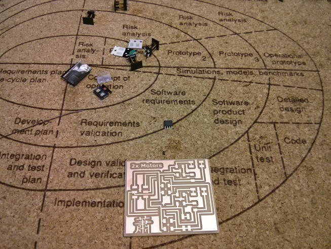
My first idea was using a L298 H-bridge, as it can handle 2 motors at the same time, having 2 data inputs and one enabler per motor. I couldn't find any locally (just found for thruhole applications) so I decided on using 2 A4953 (suggested for the assignment) on a single board. Using the example given, the following board was designed:
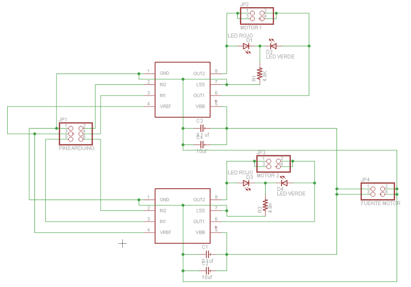
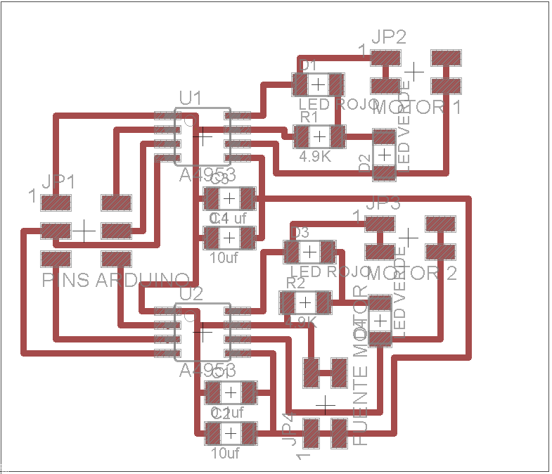
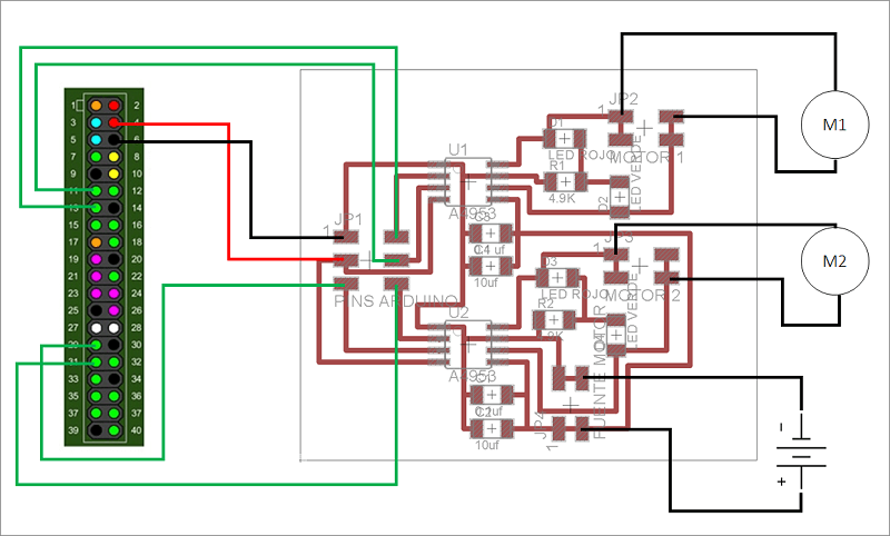
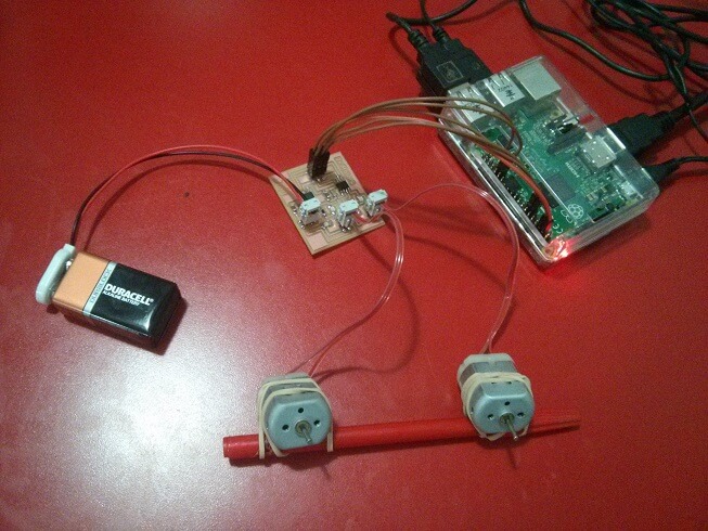
The board is designed to receive 6 inputs from my Pi 2 (or Arduino, Fabduino, etc.), having 2 data pins for each motor (to control direction), one 5V and one GND, all on a 2x3 pin. Each motor is output through a 2x2 pin (although just 2 pins are needed), and the power for the motors go to a 2x2 pin (just 2 needed). It is intended to work with a 12V transformer (which would mean changing the 2x2 pin for a female connector for the transformer), but for testing it out just a 9V battery is more than enough.
The connections are as follows:
An interesting idea suggested by a friend was adding 4 LEDs, connected in parallel to each output line. When powering a motor on clockwise it would turn on a red LED, and counterclockwise would turn on a green one.
Making the board and soldering was easy at this point.
NOTE: At first the board did not seem to work, problem ws that I used 4.9k resistances for the LED considering a 12V input, though I used just 6V on the first try and 9V later. To get it to work properly, I swapped those resistances for 1k ones.
And the final setup:
Up next was making a test code. Code was written on Nano. Basically it tests the motors on 4 scenarios: both clockwise, both counterclockwise, motor 1 clockwise and motor 2 counterclockwise, and vice versa, each for 5 seconds. To turn a motor in one direction, one of its data lines must be set to HIGH (means 1), and the other to LOW (means 0); to turn in the other direction just swap HIGH and LOW accordingly.
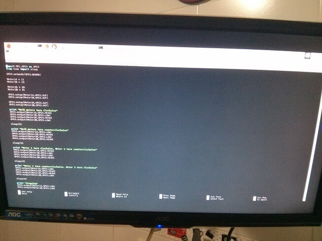
Using the following code. Notice it works using the pins I chose from the Pi 2, though it can easily be changed in a matter of seconds.
import RPi.GPIO as GPIO
from time import sleep
GPIO.setmode(GPIO.BOARD)
Motor1A = 11
Motor1B = 13
Motor2A = 29
Motor2B = 31
GPIO.setup(Motor1A,GPIO.OUT)
GPIO.setup(Motor1B,GPIO.OUT)
GPIO.setup(Motor2A,GPIO.OUT)
GPIO.setup(Motor2B,GPIO.OUT)
print "Both motors turn clockwise"
GPIO.output(Motor1A,GPIO.HIGH)
GPIO.output(Motor1B,GPIO.LOW)
GPIO.output(Motor2A,GPIO.HIGH)
GPIO.output(Motor2B,GPIO.LOW)
sleep(5)
print "Both motors turn counterclockwise"
GPIO.output(Motor1A,GPIO.LOW)
GPIO.output(Motor1B,GPIO.HIGH)
GPIO.output(Motor2A,GPIO.LOW)
GPIO.output(Motor2B,GPIO.HIGH)
sleep(5)
print "Motor 1 turn clockwise, Motor 2 turn counterclockwise"
GPIO.output(Motor1A,GPIO.HIGH)
GPIO.output(Motor1B,GPIO.LOW)
GPIO.output(Motor2A,GPIO.LOW)
GPIO.output(Motor2B,GPIO.HIGH)
sleep(5)
print "Motor 1 turn counterclockwise, Motor 2 turn clockwise"
GPIO.output(Motor1A,GPIO.LOW)
GPIO.output(Motor1B,GPIO.HIGH)
GPIO.output(Motor2A,GPIO.HIGH)
GPIO.output(Motor2B,GPIO.LOW)
sleep(5)
print "Stopping"
GPIO.output(Motor1A,GPIO.LOW)
GPIO.output(Motor1B,GPIO.LOW)
GPIO.output(Motor2A,GPIO.LOW)
GPIO.output(Motor2B,GPIO.LOW)
GPIO.cleanup()
I saved it as "test_code_2_motors.py" so at LXterminal just typed "sudo python test_code_2_motors.py" and the motors start running.
In the video, though the motion of the motors cannot be seen clearly, the change of direction can be seen as the signal LEDs turn on and off accordingly.
UPDATE: The board created ended up being quite useful. I know that Arely Amaut (ESAN) and Roy Livne (Israel) use it for their final proyect. I also intend to, in the future, make a mashup of my last version Fabduino with this board, to make something like the Romeo One-in-All-Controller (DFROBOT).