Interface and Application Programming
This week's assignment, was to write an application that interfaces with an input or output device
First I thought that would be cool to work on an interface for controlling a CNC machine since our group at Fab Lab UNI is planning to build one on the following weeks, but later I realized that the time was too short and I would need more knowledge for achieving that, so finally y lowed my goal and decided to design an interface for testing the movement of the machines's axis by controlling manually the stepper motors.
I looked around on the internet trying to find the best way for doing this in short time finally a I saw two possible options for achieving what I wanted to do, first using Processing, and the other one was to use NI’s LabVIEW, I decided to use LabVIEW because I saw allot of nice virtual interface for controlling different outputs with Arduino, and the programing was graphic instead of written
For using LabVIEW + Arduino you will need the following:
- NI's VI Package Manager
- NI's LabVIEW 2104
- NI's LabVIEW Interface for Arduino Toolkit
- NI's NI-VISA 5.4
You can download all this for a trial version or educational version at NI's website
- Arduino IDE 1.0.5-r2 (won't work on newer versions)
- Arduino Board
You'll need to upload the LabVIEW Interface for Arduino Toolkit Firmware to your board, you can find it in the following folder: C:\Program Files\National Instruments\LabVIEW 201x\vi.lib\LabVIEW Interface for Arduino\Firmware\LIFA_Base (for Windows) the file is named LIFA_Base.ino
When the upload is complete you can open LabVIEW and start designing your interface if you are new like me you can star by looking and modifing the example files. I worked with the Stepper Motor example as the base of my Interface
My Interface Design (X.CULPT is the name of the machine)
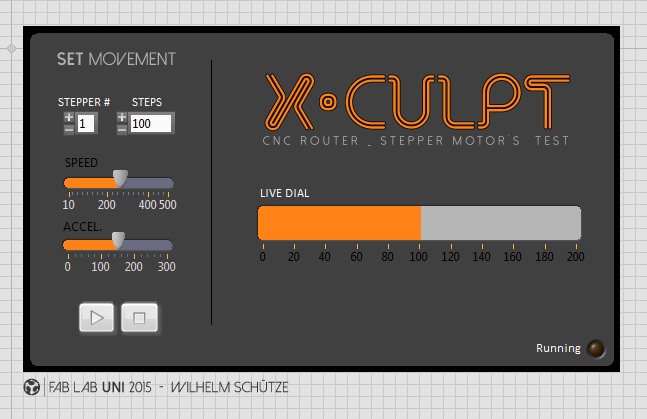
As you can see is divided in two parts a live dial for free jogging and a programmable part for setting a number of steps to run, you can also set the speed, and acceleration, and use your pc's keyboard for controlling single steps by pressing PGUP and PGDN.
Block Diagram (code)
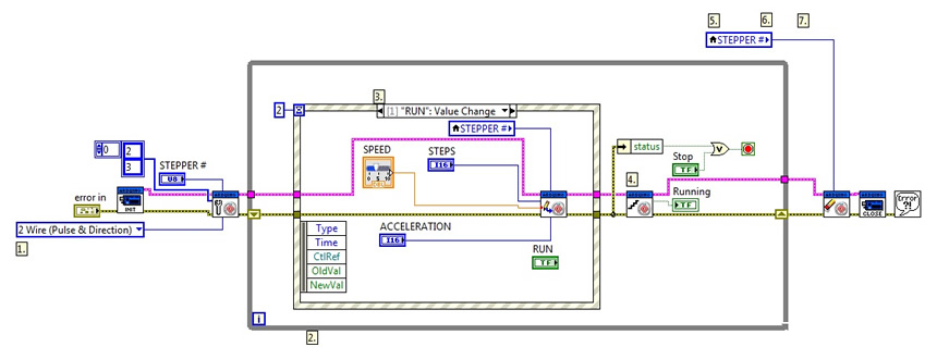
The block Diagram section is where you start yo have to create a loop structure (gray square) and add a INIT and a CLOSE functions for arduino + all the virtual components (sliders, knobs, buttons, metters , etc.) and the output or/and input pins of the board acording to de fisical components (supported components according to the libraries).
Wiring
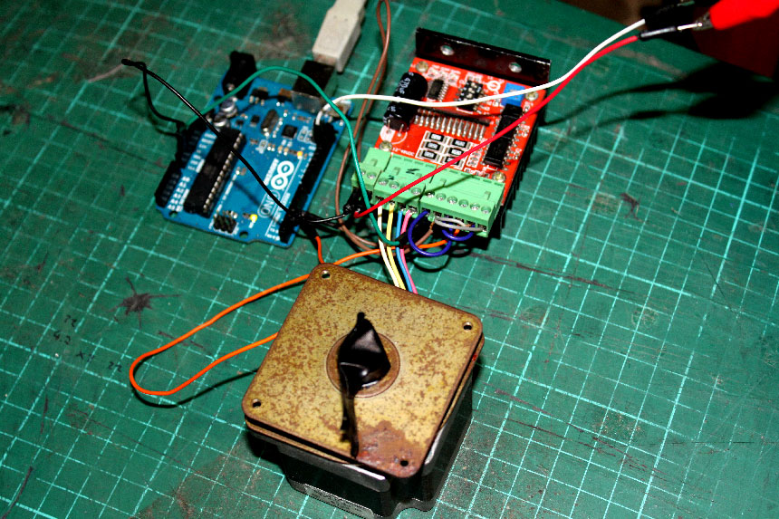
I used an Arduino UNO board + a TB6600 driver for controlling the motor I hooked DIR to D3 and STEP to D2 on Arduino. The driver is powered by an ATX 12V power supply and the Arduino board is powered by the USB port, all the GND are wired together. 4 wire drivers configurations are also supported by changing a toggle on the block diagram.
Here is a video showing all the functioning of the interface: