Networking and Communications
This week's assignment, was to design and build a wired &/or wireless network connecting at least two processors.
I decided to build the "Hello.bus.45" example with some modifications, I wanted to play a tone along with the falsh of the LED, but I had some problems in the way and I ended up by making the standard version and I added some labels on the boards.
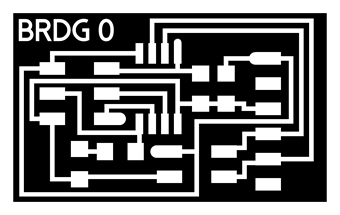
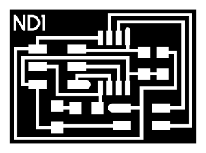
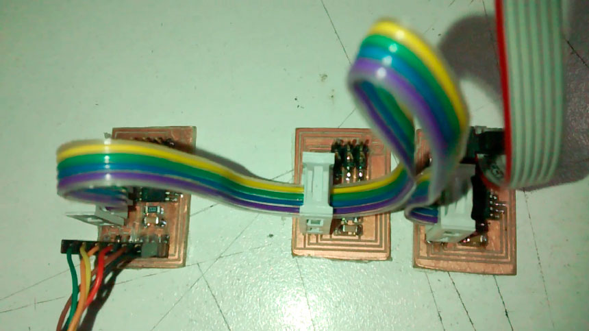
Here are the leabeled boards :

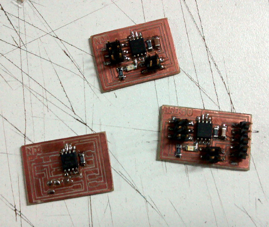
I milled the boards and soldered the components in place,
BOM:
BRIDGE:
1x Attiny45
1x 1K ohms SMD resistor
1x 499 ohms SMD resistor
1x LED smd
1x 1uF Cap
1x 2x2 Pin Header
1x 2x3 Pin Header
1x 1x6 Pin header
NODE:
1x Attiny45
1x 1K ohms SMD resistor
1x 499 ohms SMD resistor
1x LED smd
1x 1uF Cap
1x 2x2 Pin Header
1x 2x3 Pin Header
For a tutorial see this page at Fablab's UNI site (in spanish)
Here are my boards with the soldering almost finished:
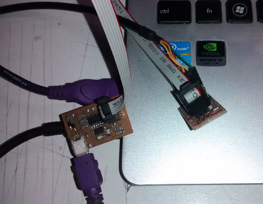
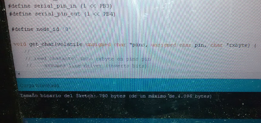
Next, I loaded Neil's code using the arduino's IDE (you have to had installed the Attiny libraries) in the bridge board with the FabISP+the FTDI cable conected.
You have to replace this line of the code in the node boards:
#define node_id ‘0’
For node 1 : #define node_id ‘1’
For node 2 : #define node_id ‘2’
Happy to see that the code loaded well,
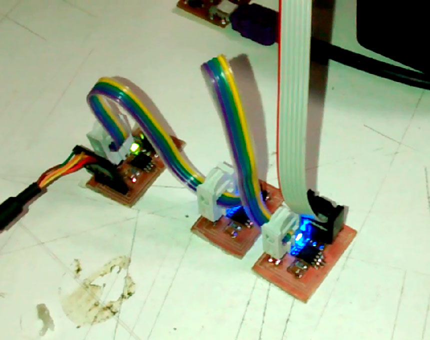
After the code is loaded on the bridge, connect the flat cable between the bridge and the first node on the 2x2 pin headers and burn the code again but with the node id number changed and repeat this step with the final node board (all 3 connected+ the ISP + the FTDI).
Finally open the serial monitor in 9600 baud rate and test that the program works, you should get node 1 response when pressing 1 and node 2 when pressing 2 on the keyboard, and also the leds will flash.
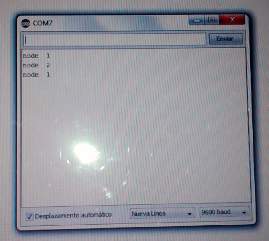
Everything went well.
Here is a video showing how it works: