Input Devices
This week's assignment, was to measure something: add a sensor to a microcontroller board that you've designed and read it.
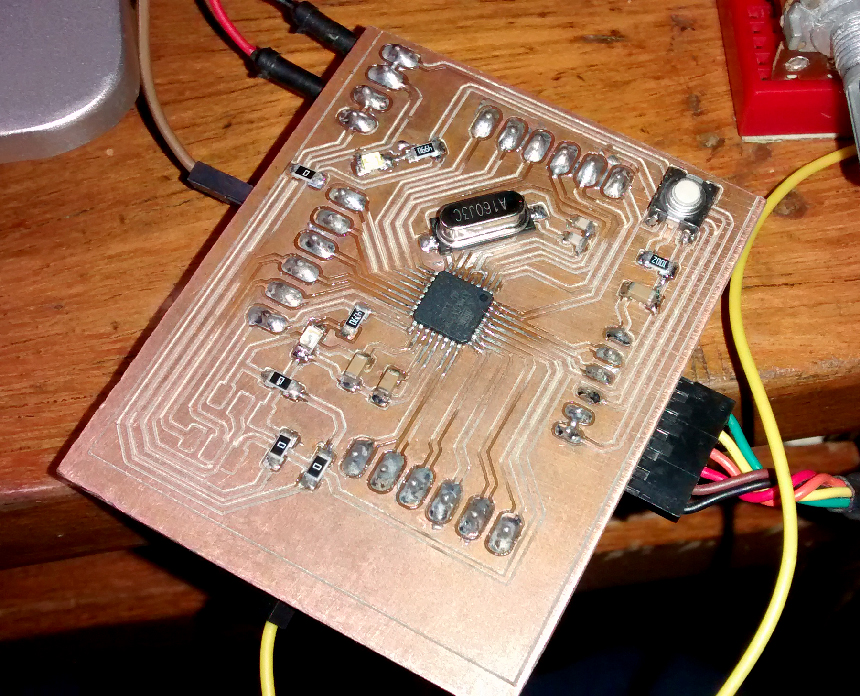
This week I decided to make a "fabduino" board, for being able to plug and unplug diferent inputs easily, my board is based on Jose de los Rios's version, this version has 3 components that are not on the inventary, but are easy to find and cheap, (a 16Mhz Crystal and 2 22pf capasitors) I've made a few minor changes, I replaced the pin headers with screw terminals, I changed the thru-hole cristal and caps with SMD components and moved the power terminal.
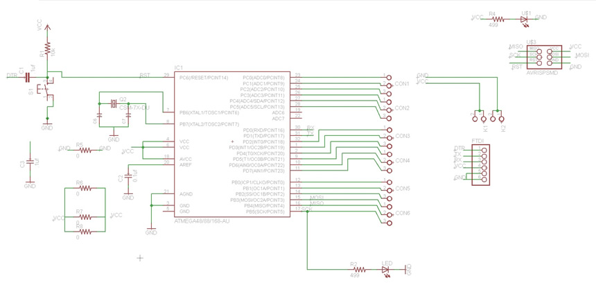
Schematic
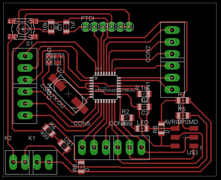
Board
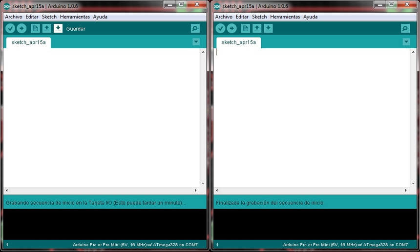
I had some problems with teh bootloader because I used the chip Atmega328 instead of the Atmega328p, but searching on the internet i solved it by changing the signature on the avrdude.conf, this is what I found on internet:
"Problem:
Avrdude dislikes your lovely 328-PU chips and says "avrdude: Yikes! Invalid device signature." or "avrdude: Expected signature for ATMEGA328P is 1E 95 0F"
Solution: This problem happens becoz ur arduino uses 328p - pu and if u bought 328pu(a couple dollars cheap).
The soln is to modify Arduino > hardware >tools>avr>etc and open avrdude.conf file as word document.keep backup of this file incase u mess up.
find 1E 95 0F text under Atmega328 and change it to 1E 95 14 and save.
restart arduino environment and burn bootloaders on all ur chips.use status leds as mogul said.they help a lot.
After burning change the text in avrdude.conf file back to 1E 95 0F and restart arduino ide.Then u can uplode code normally."
After doing this all worked well
When the board was ready I tried diferent inputs like buttons, switches , potentiometers and LDRs.
Different simple connections:
switch connection: leg1 to VCC, leg2 to pin8, 1k resistor from leg2 to GND
button connection: leg1 to VCC, leg2 to pin8, 1k resistor from leg2 to GND
pot conection: leg1 to VCC, leg2 to pin A0, leg3 to GND
LDR connection: leg1 to GND, leg2 to A0, 1k resistor from leg2 to VCC
And for all, speaker connected: 1leg to GND and the other to pin9
Code for switch and button:
Code for Pot and LDR
Here is a video showing the diferent inputs