W18. Project Development
My project is:
acoustic panel by ak 0.0
An acoustic Panel that could transform at a certain level of decibels from a flat piece in to a tridimensional object. This panel will improve the acoustic of a room and will use the minimum space from ceiling.
1. THE IDEA
This is the process I follow for the development of my project. In the beginning my goal was to design and build an acoustic panel that could be used as a wall or division or as a ceiling panel.
As I am new in the use and production of electronic devices I decided to explore the use of sensors and a mechanical device to move a a single module of that panel. In the fase I (Fab Academy) I will design and build an structure, the mechanism for movement and a microcontroller board.
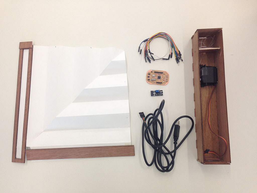
The elements that I will use are:
- sound sensor (W 503 DC009)
- servo motor (Tower Pro MG996R 180º Digi Hi Torque)
- my version of Daniele Ingrassia fabduino kit (Shasatshakit with a microprocessor 328AU P)
- connection cables
- structure: 3mms wood sheet for the box, in this fase paper for the panel, sewing thread.
The process and machines I will use:
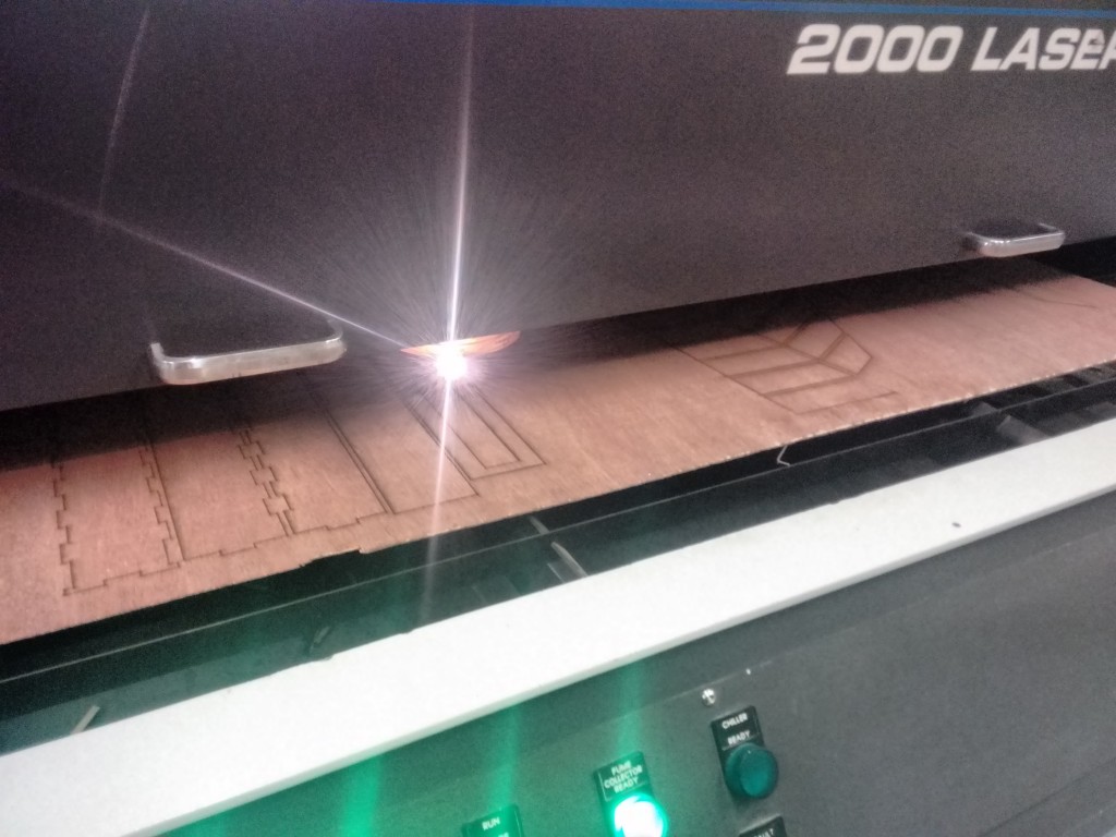
- laser cutting (structure)
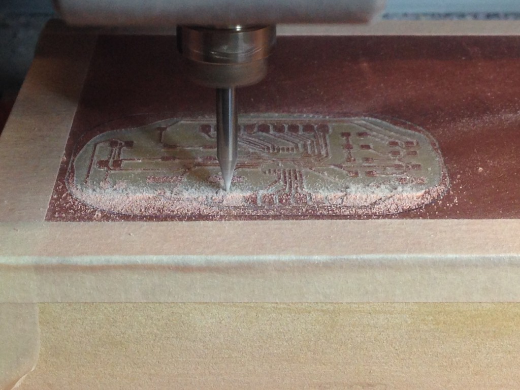
- milling (pcb)
- 3d printing (mechanical)
2. THE PROTOTYPE – acoustic panel by ak 0.0
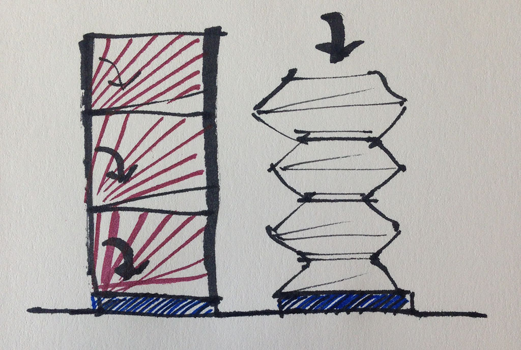
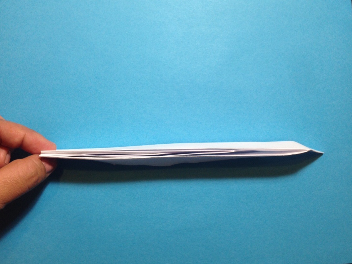
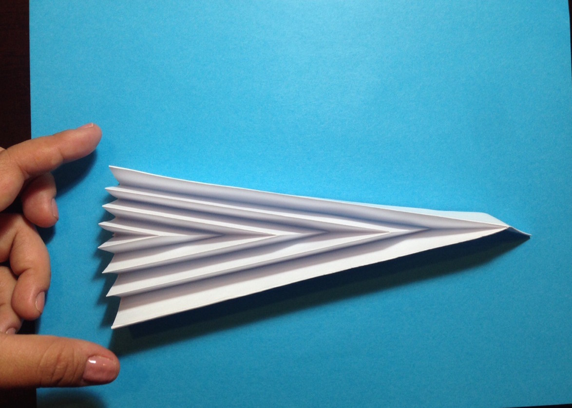
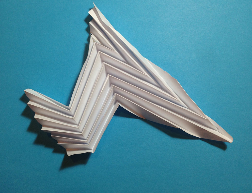
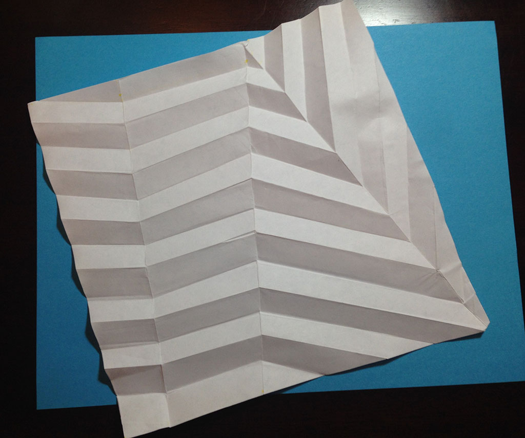
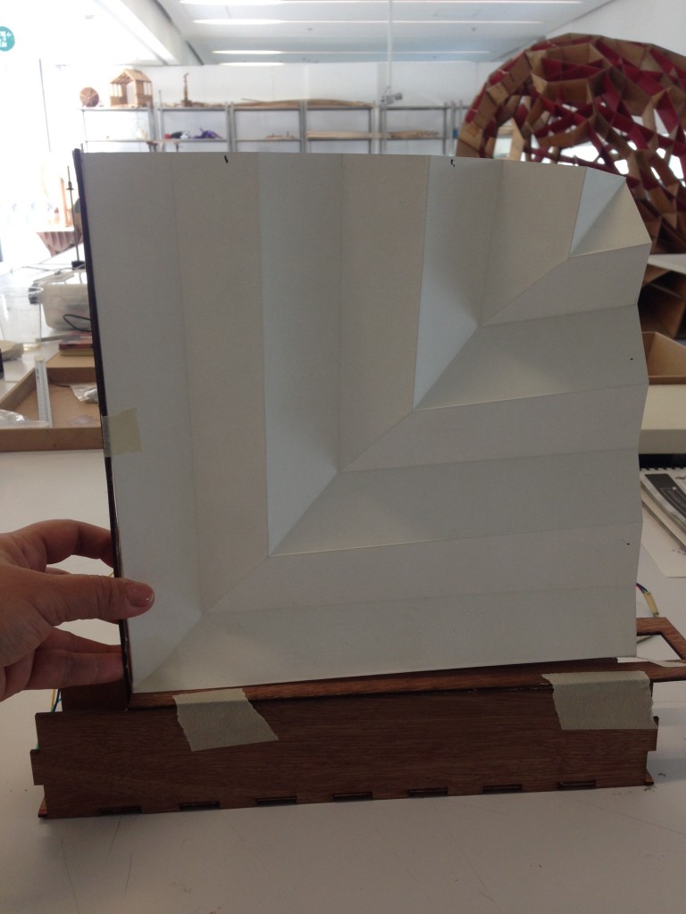
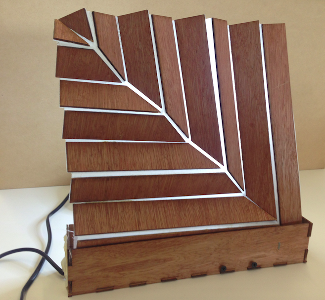
I designed the module using an origami form so the piece could be folded and unfolded easily by a simple structure with a single point of contact. The material to use for the panel in this fase 0.0 is paper and for the structure I used wood. The structure will move the folded piece at a moment when the sorrounding sound gets noisy (in next fase I will improve the combination of the code in order to get a better control of the sound).
The panel:
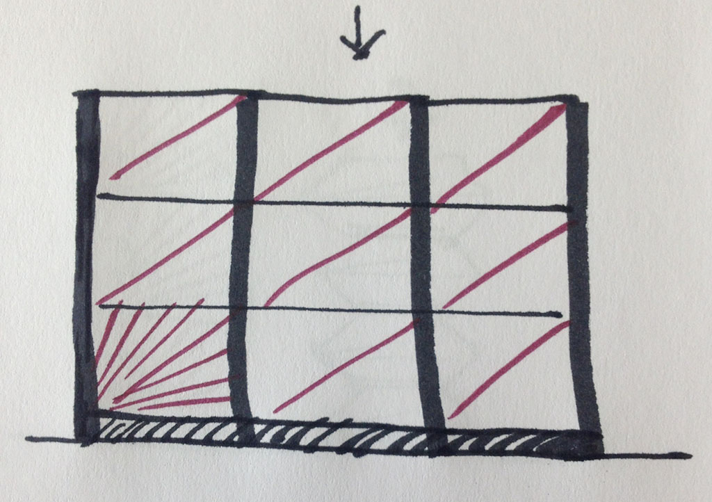
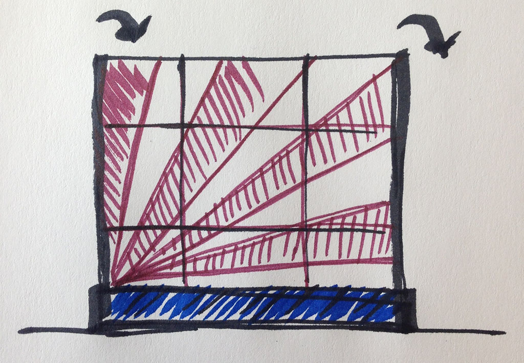
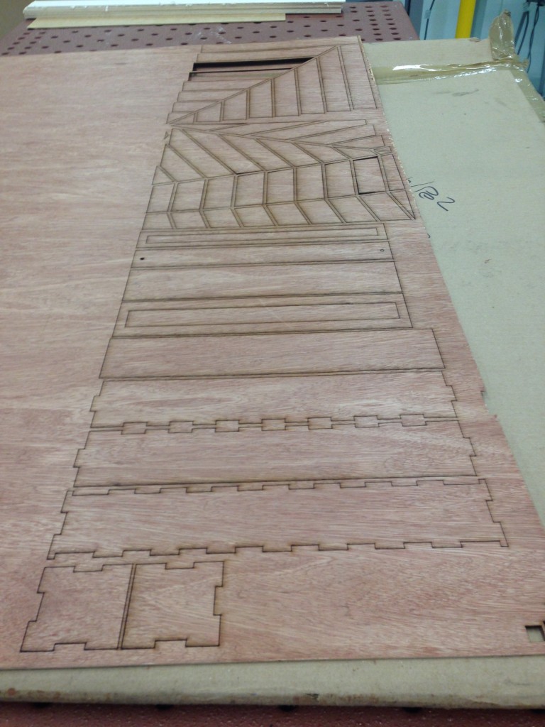
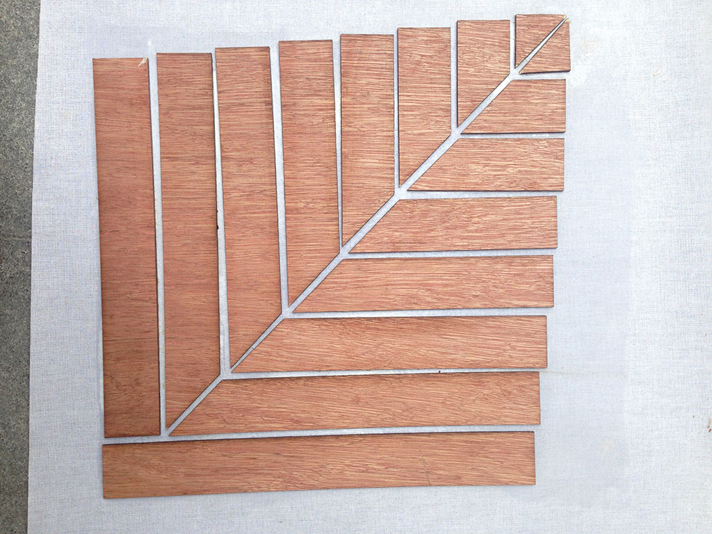
I experiment some of the folding techniques by Paul Jackson. I selected the ones on the next images, I think that this models could be easy to fold and unfold by one point force.
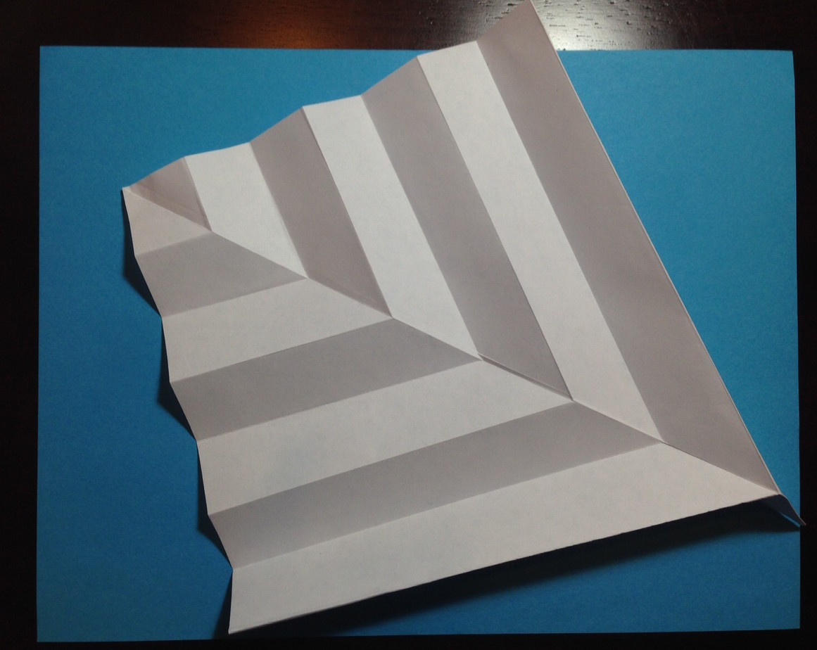
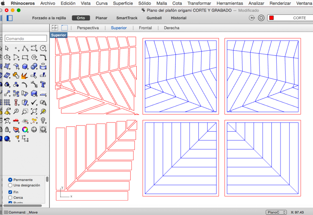
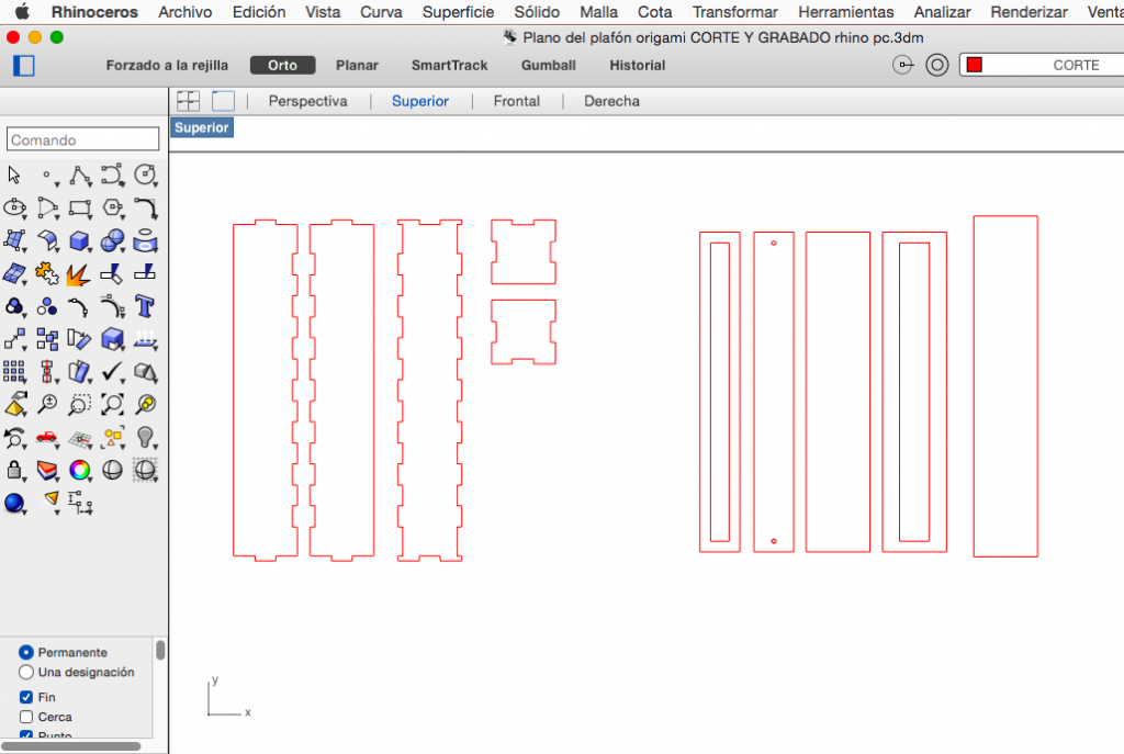
I used Rhinoceros to draw the panel pieces of the single module, in the future I want to experiment not only with cotton paper but also with fabric and wood. I think those materials will improve the acoustic absorption. In Rhinoceros I have an example to engrave (blue line) and pieces to laser cut (red line).
The structure:
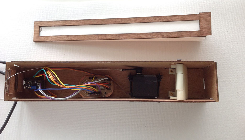
I decided to use wood for the structure, it will be not that expensive and also it will be resistant and easy to build. First I continue designing it by defining the size of the space I will need to contain the electronics and the motor as well as the panel. The little box (container or case) will have 6 cms of height and width; and 32 cms of long. The wood I am using is banak with 6mms of thickness. The line I am using is color red because I will use the laser cutting.
I am using press and fit to assembly the pieces of the box. file.dxf
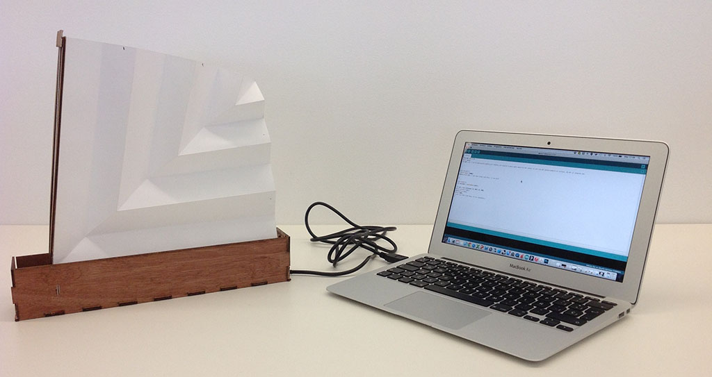
I assembly the pieces of the box, the paper panel and the structure to check the dimensions and the mechanism.
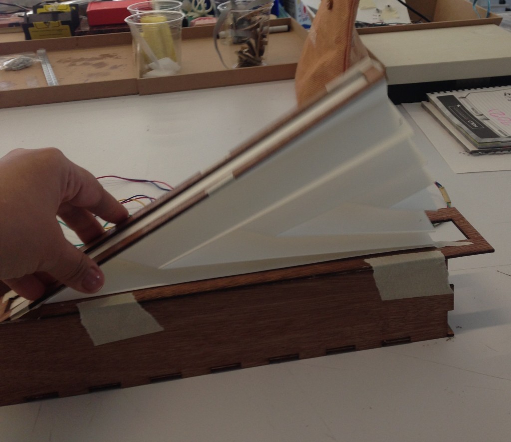
It seems to be working perfectly with the dimensions so I decided to design a hinge to move the panel in an axis. I tried an arduino and also a fabkit to move the servo motor with the panel and the box.
After the first test I have to redesign the border sides of the box and ad a hinge.
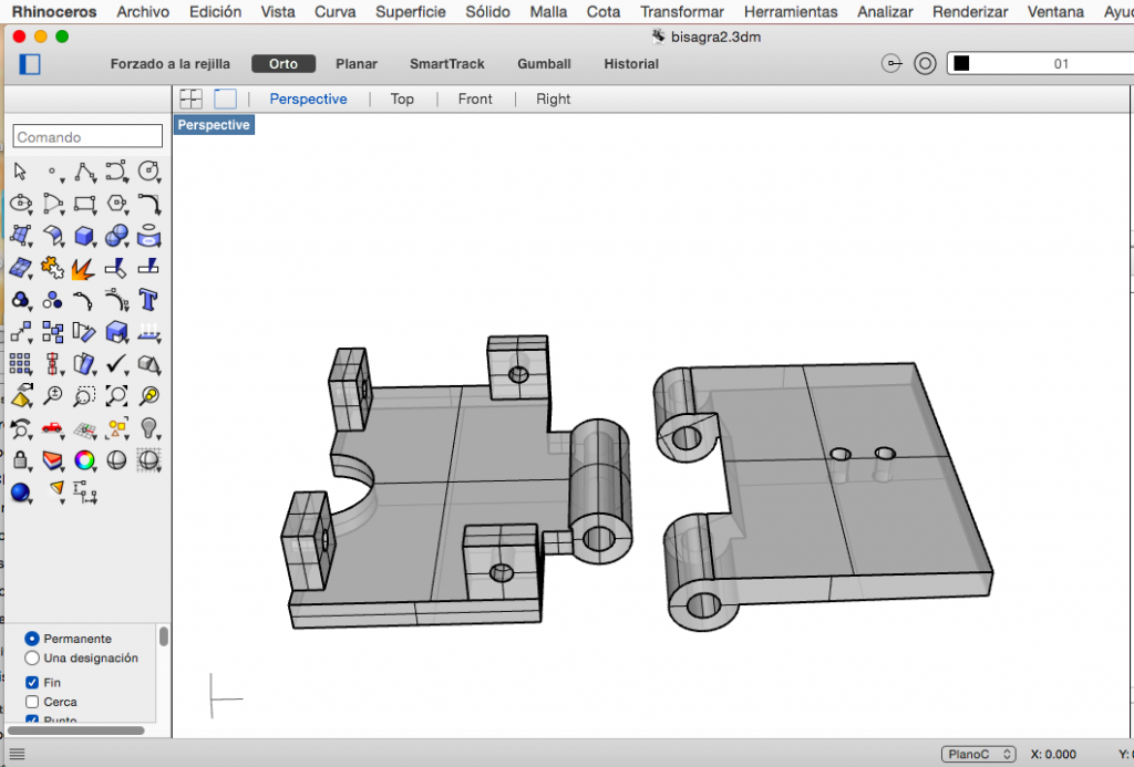
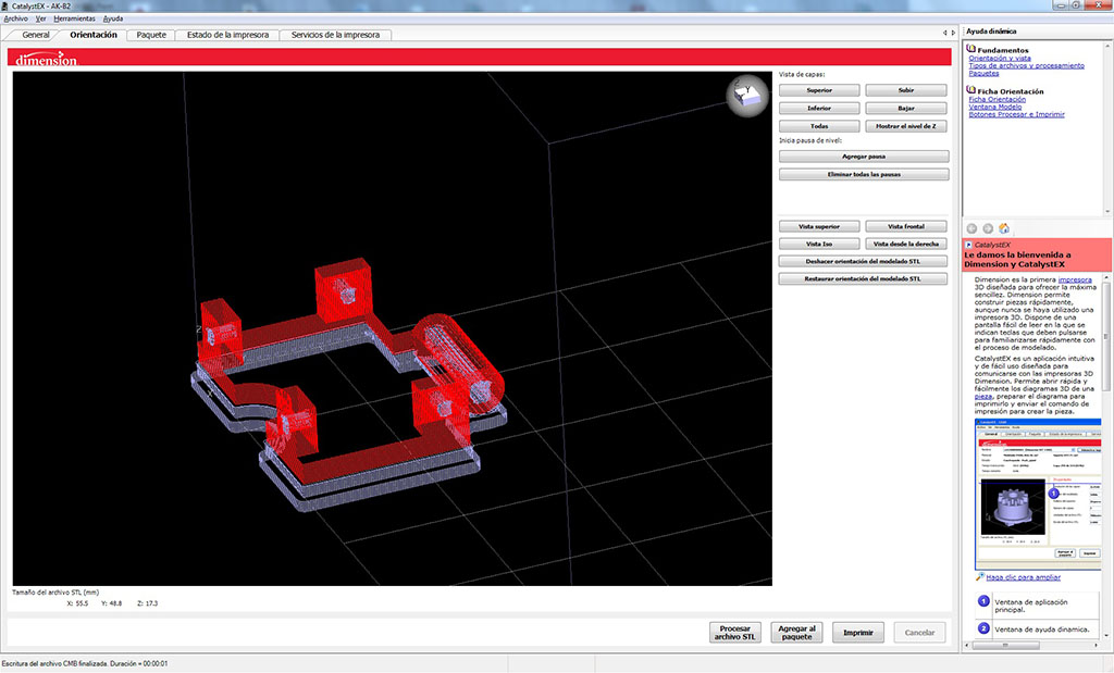
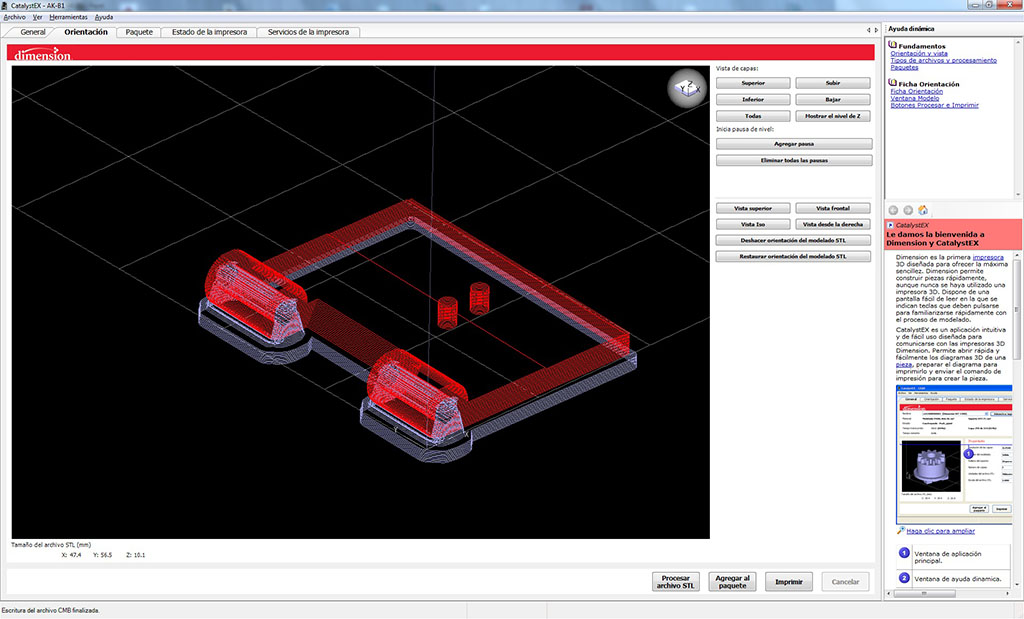
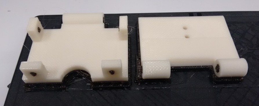
I used rhino again but for the hinge I needed to work in 3D for 3D printing. I used Rhinoceros to draw and design; and the Uprint to print the object. file.stl

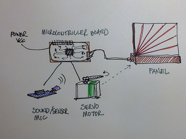
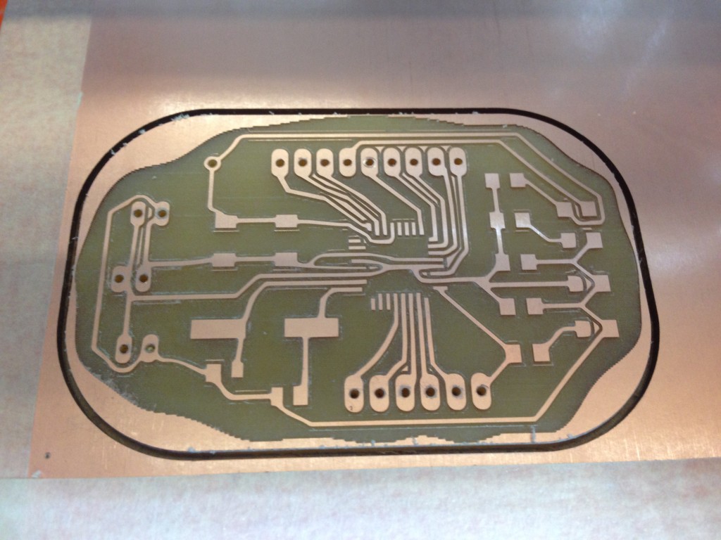
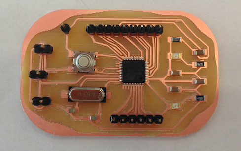
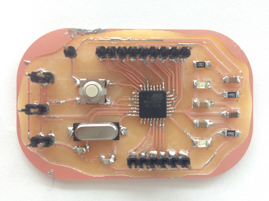
Electronics and Mechanism
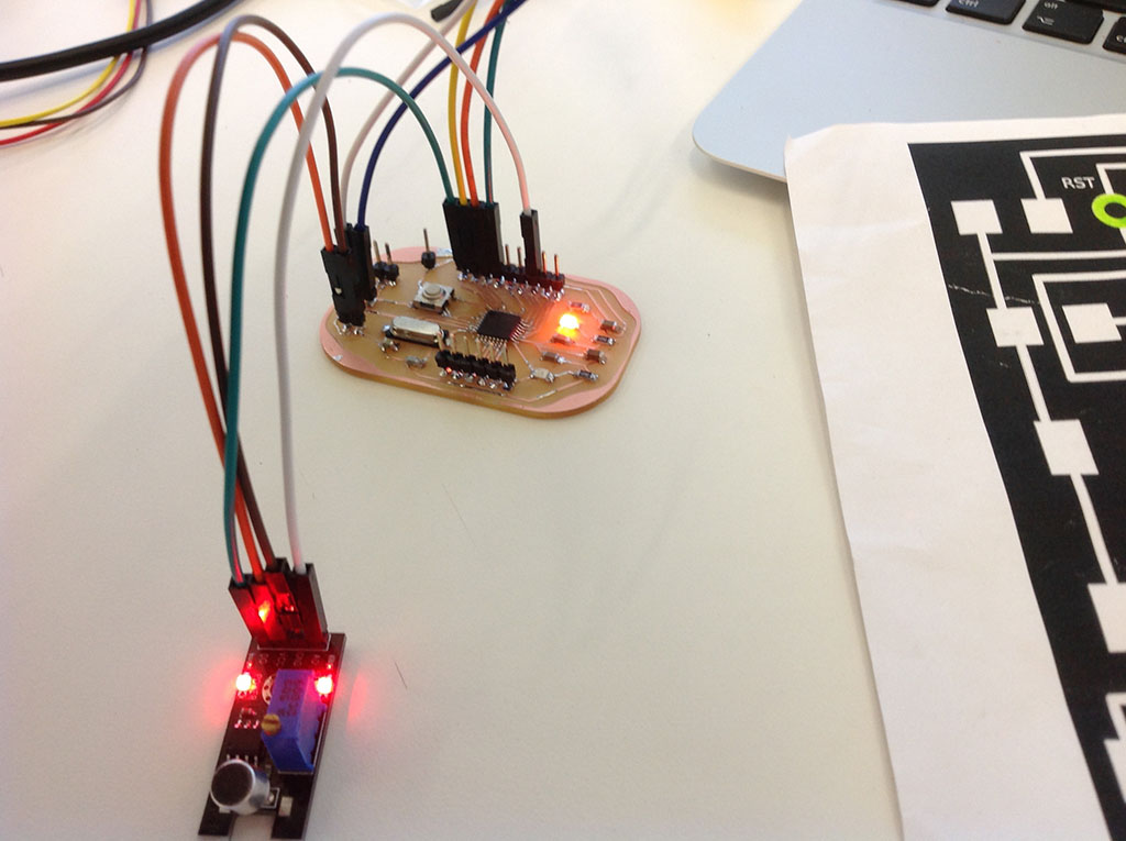
I needed a microcontroller to move a servo and also for the mic or sound sensor. I decided to use Daniele Ingrassia’s Fab Kit call satshakit, we tried it and work perfect but not exactly for what I need. As I am using a servo and a sensor I will need to add power (vcc and ground jacks) and modify the routes to have the exact number of pins I need.
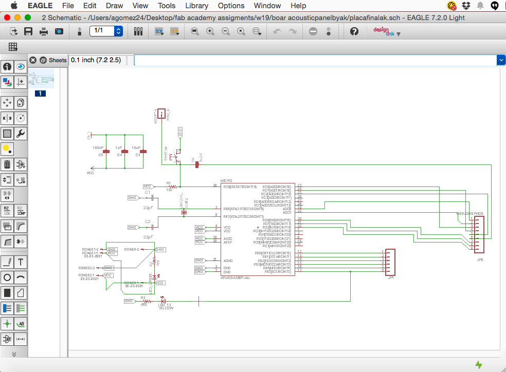
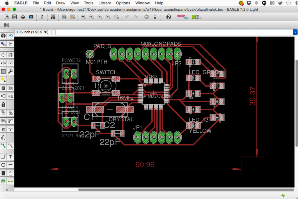
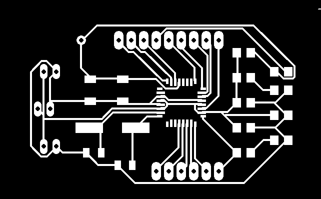
board, schematic, png, edge, routes and perforations.
BOM:
list of components I used in my microcontroller acoustic panel by ak and the rest of the project:
| materials | units | cost | supplier | |
| 3 mms wood panel (plywood) | (a piece of 40cmX122cms) | 1 | $3.00 | local store |
| servo motor | (Tower Pro MG996R 180º Digi Hi Torque) | 1 | $19.95 | adafruit |
| mic/sound sensor | 3-6v module sound sensor | 1 | $3.00 | 5hertz local store |
| jumper female to female (x10) | 932-MIKROE-511 | 2 | $3.90 | mouser |
| ftdi serial usb | 768-1028-ND | 1 | $17.95 | adafruit |
| microcontroller | ||||
| Atmega328P-AU | 556-ATMEGA328P-AU | 1 | $3.93 | Mouser |
| crystal 16 Mhz/ 18 pf | 815-ABLS3-16MD4YT | 1 | $16.25 | Mouser |
| switch | 311-499FRCT-ND | 1 | $0.59 | Digikey |
| led green | 859-LTST-C150GKT | 1 | $0.18 | Mouser |
| led red | 941-CLV1LFKBC7673673 | 1 | $0.21 | Mouser |
| 10K resistor | 603-RC1206FR-0710KL | 1 | $0.01 | Mouser |
| 499 resistor | 603-RC1206FR-07499RL | 2 | $0.03 | Mouser |
| 22pf capacitor | 77-VJ0805A220JXGAT5Z | 2 | $0.46 | Mouser |
| 10uf capacitor | 963-GMK316F106ZL-T | 1 | $0.96 | Mouser |
| 1uf capacitor | 810-C3216X7R1H105K | 1 | $0.22 | Mouser |
| 0.1uf capacitor | 80-C1206C104KAR | 2 | $0.21 | Mouser |
| 1×6 jumper | ED65508-ND | 1 | $0.18 | Digikey |
| 1×9 jumper | ED65508-ND | 1 | $0.27 | Digikey |
| 1×2 jumper | ED65508-ND | 3 | $0.06 | Digikey |
| 1×1 jumper | ED65508-ND | 1 | $0.03 | Digikey |
| $71.38 |
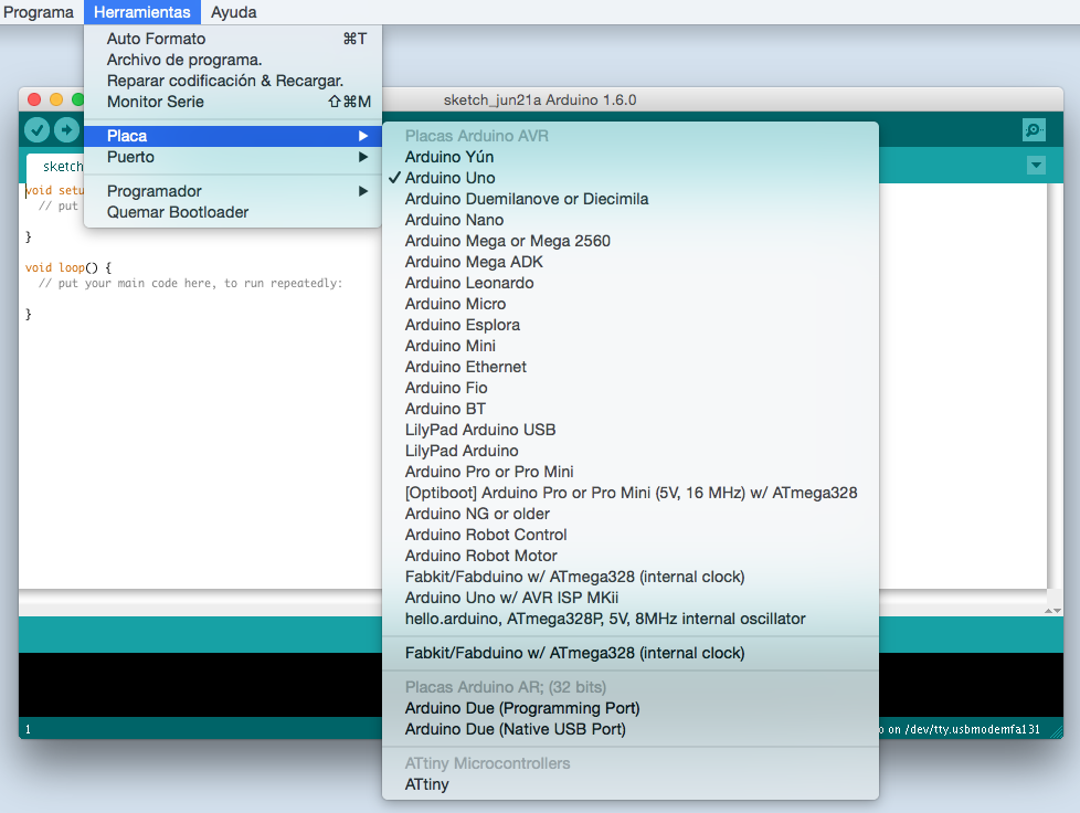
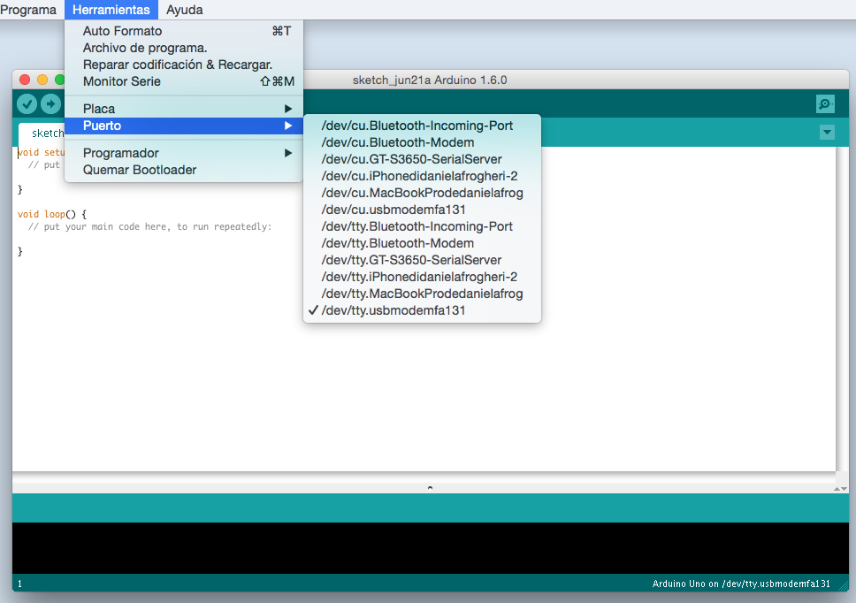
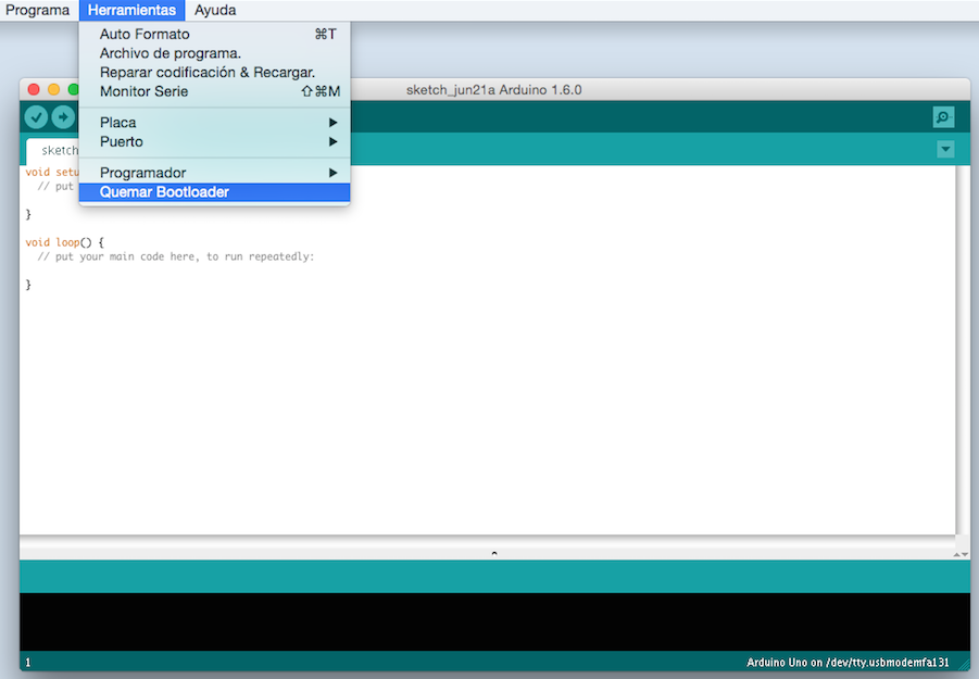
Programming
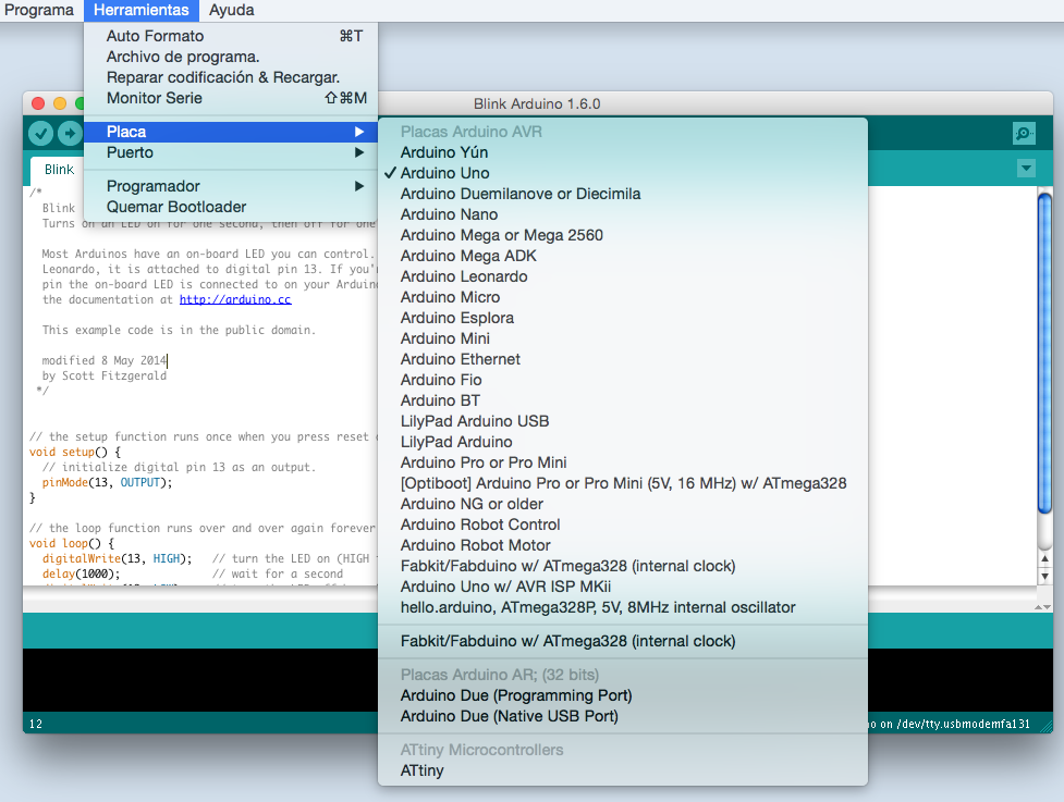
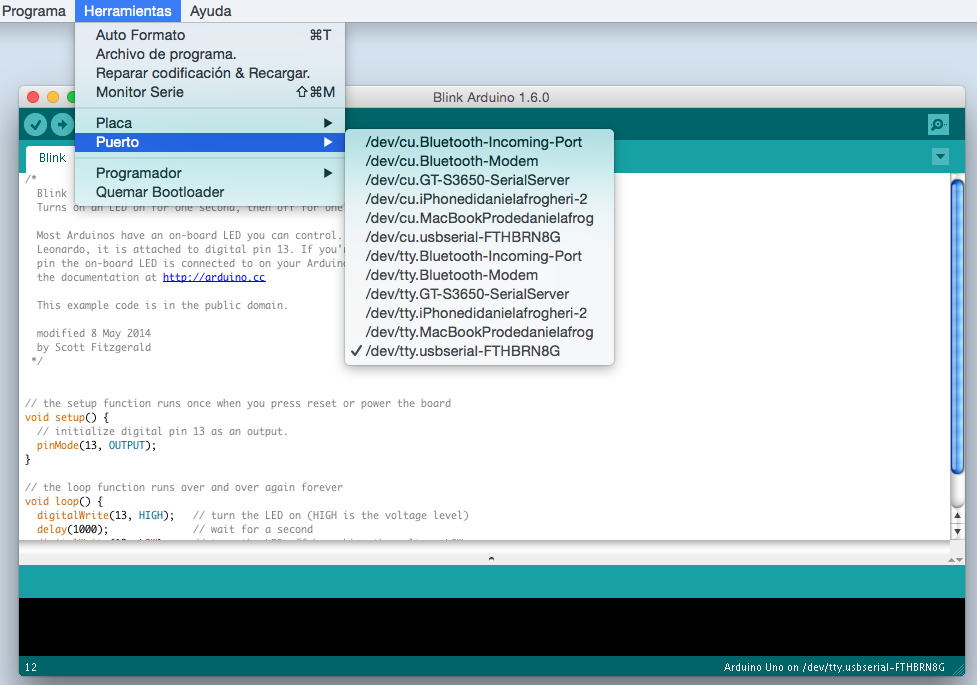
To program my microcontroller I used Arduino Uno as ISP to boatloader the Atmega. I follow instructions adding a capacitor of 10uf to my arduino board and follow the process to burn boatloader.
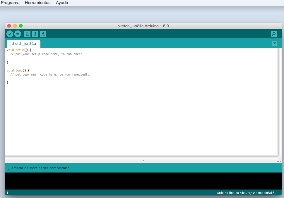
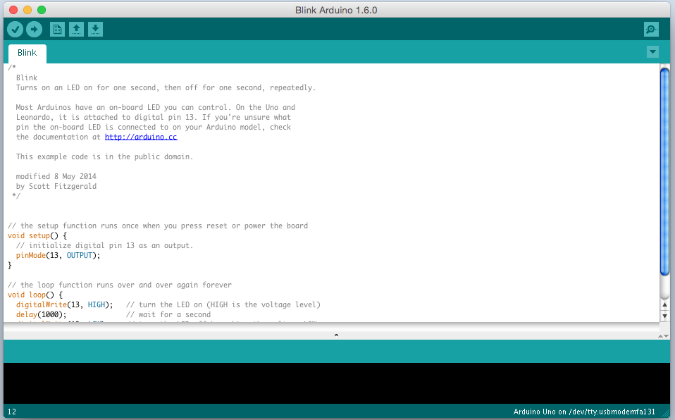
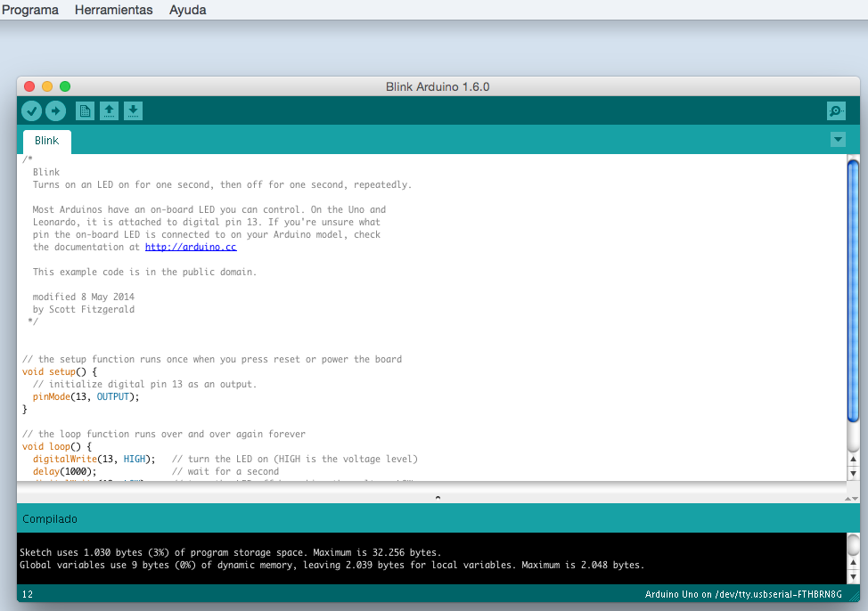
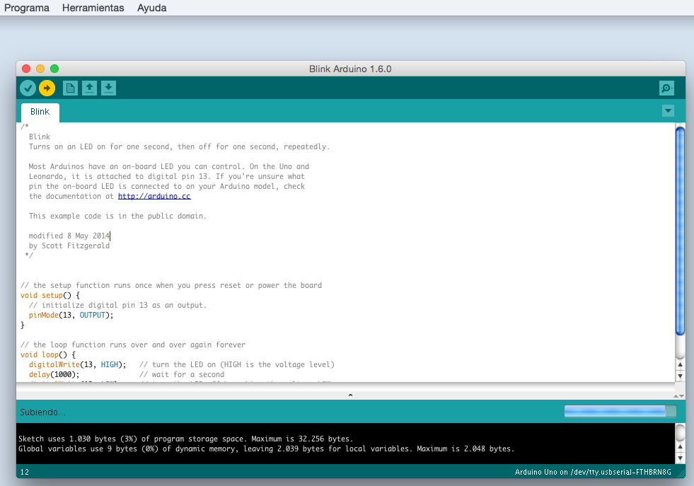
After the boatloader was completed I test the microcontroller with the sketch “blink”.
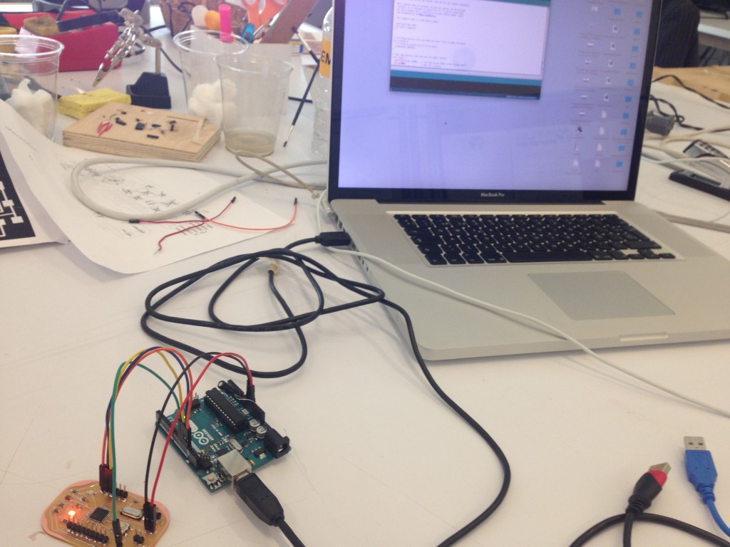
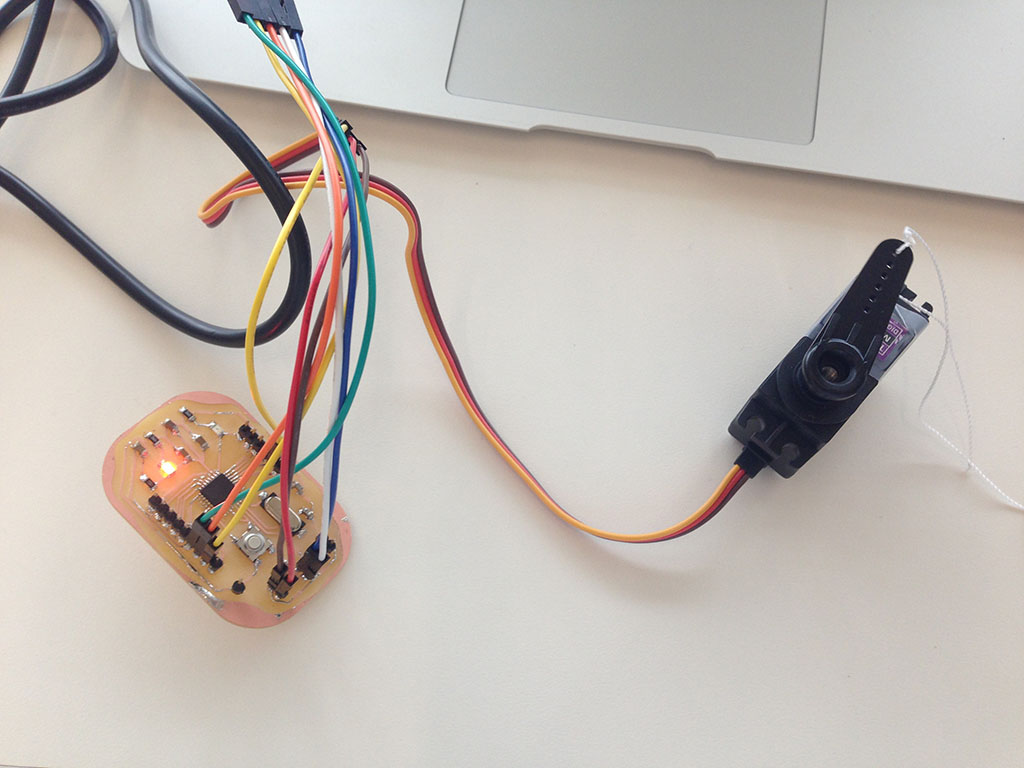
After finishing the process I connected the servo motor with the microcontroller and also the sound sensor to check the movement expected.
The code that I used as a test is in the sketch examples of the Arduino IDE, I selected servo knob and modify angle and delay fron 15 to 100.
- #include <Servo.h>
- Servo servo;
- int pot = 3; // pin A3 para potenciometro pin interno; pin digital 6 para cable amarillo del servo, el pin izq del potenciometro es voltaje, de ahí al arduino uno.
- void setup() {
- Serial.begin (9600);
- servo.attach (6);
- }
- void loop() {
- int valorpot = analogRead (pot);
- int val = map (valorpot, 0, 1023, 0, 180);
- Serial.println (val);
- servo.write (val);
- delay (100);
- }
and for sound I used as a test a code suggested by adafruit from the microphone amplifier:
- const int sampleWindow = 50; // Sample window width in mS (50 mS = 20Hz)
- unsigned int sample;
- void setup()
- {
- Serial.begin(9600);
- }
- void loop()
- {
- unsigned long startMillis= millis(); // Start of sample window
- unsigned int peakToPeak = 0; // peak-to-peak level
- unsigned int signalMax = 0;
- unsigned int signalMin = 1024;
- // collect data for 50 mS
- while (millis() - startMillis < sampleWindow)
- {
- sample = analogRead(0);
- if (sample < 1024) // toss out spurious readings
- {
- if (sample > signalMax)
- {
- signalMax = sample; // save just the max levels
- }
- else if (sample < signalMin)
- {
- signalMin = sample; // save just the min levels
- }
- }
- }
- peakToPeak = signalMax - signalMin; // max - min = peak-peak amplitude
- double volts = (peakToPeak * 3.3) / 1024; // convert to volts
- Serial.println(volts);
- }
I got a great result, the microcontroller moves the servo and the panel; and it captures sound levels; also the structure is strong enough to mantain the panel in its place.
3. WHAT’S NEXT:
I will continue working with the code for the sound sensor, I want to have the movement by the sound level. At this moment both codes work perfect but separated.
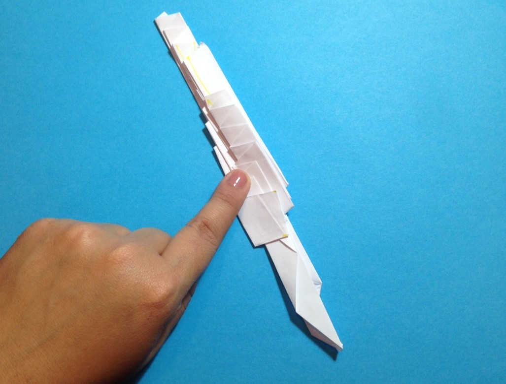
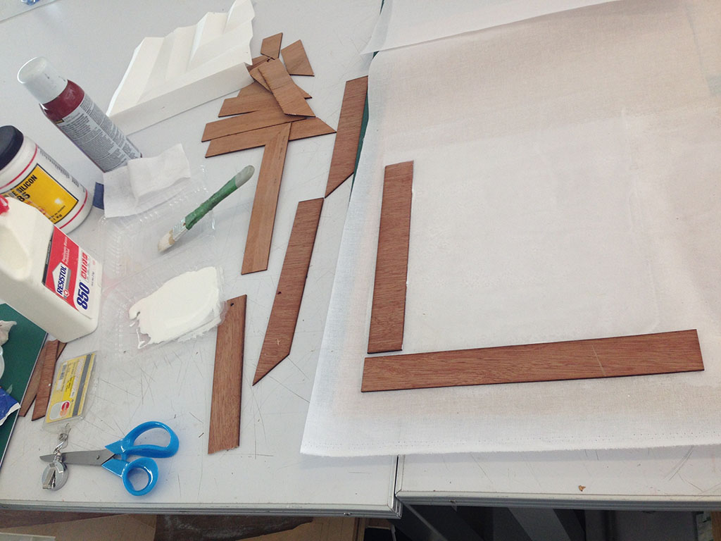
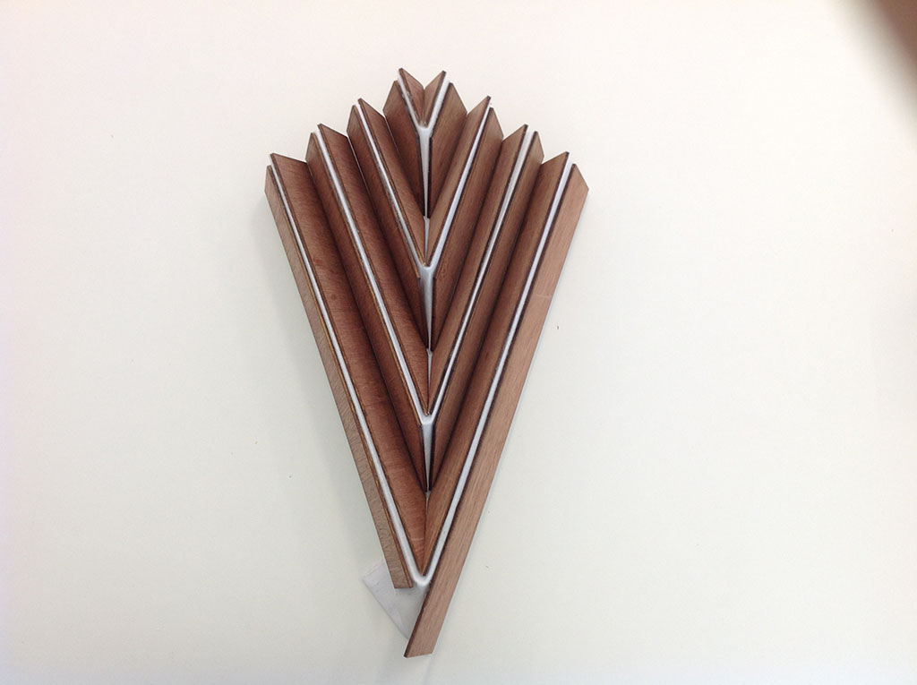
I also want to continue working with other materials, as I mention before I experiment with wood + fabric for the panel. I have the piece but I will need to change the servo motor to a bipolar stepper motor or a bigger servo, but it will make my project real expensive.
Here is the panel which I will continue working. It looks great but it is to heavy for the structure and the servo motor.
4. CONCLUSION:
I realize after 19+ weeks that this journey was amazying, frustrating sometimes but the balance is that I have learned a lot. I was a beginner in almost every subject of this course and now I feel that I can make “almost” anything. I have enjoy every assignment and the most important part of it was to work at a side of a great team: Fab Lab Monterrey / CRGS and the great people that students from all over the world are.
I am sure that I will continue studying and experimenting all that I have started in the Fab Academy 2015.