W. 11 Add an output device to a microcontroller board and program it to do something
BOARD + OUPUT DEVICE + ACTION
This week I made a stepper motor hello, a servo hello device to move a motor and after two frustrating attemps with the motor drivers I decided to make also a hello LCD device.
As I will use an small motor (bipolar or a servo) for my final project (acoustic panel) I first decided to made an output for that..
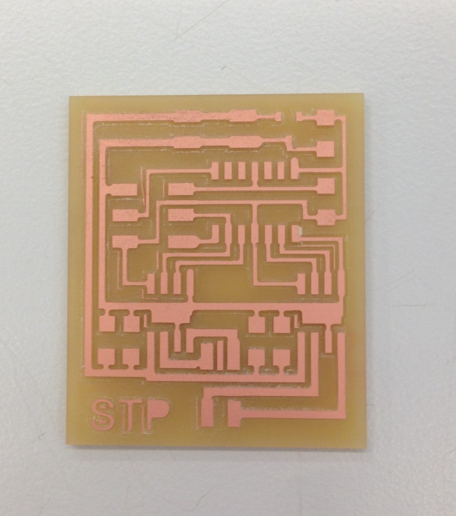
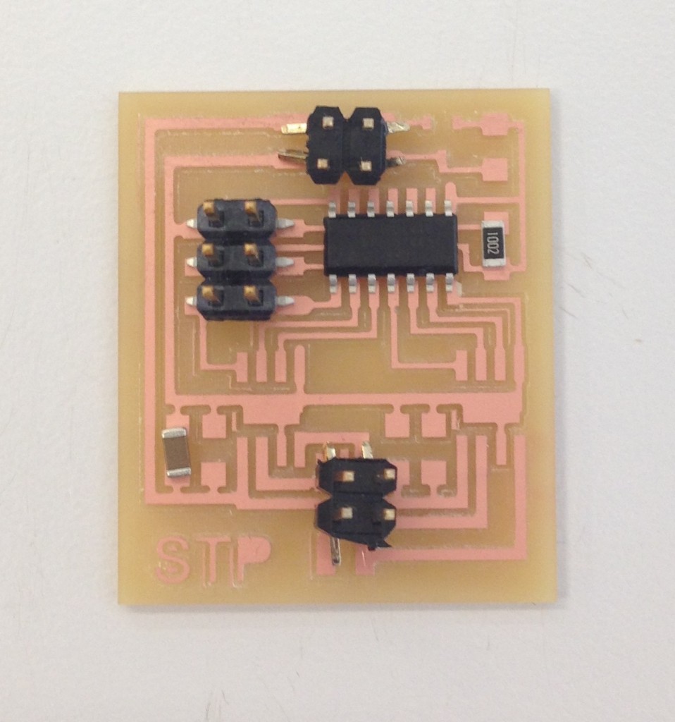
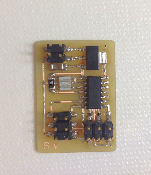
1. STEPPER MOTOR BOARD
The stepper motor (bipolar) has the following components:
- 1 Attiny 44 microprocessor
- 2 IC MOTOR DRIVER PAR 8SOIC
- 1 10K Ohms Resistor
- 1 1uf Capacitor
- 1 0.1uf Capacitor
- 2 10uf Capacitor
- 1 2×3 connector
- 2 2×2 jumper connector
- Regulator of 5 v IC 5.0 100MA LDO VREG SOT23
I cut the board in the SRM-20 and Modela software with the following documents from the fabacademy archive:
board, components, traces, interior
After the board was ready I place the components available while waiting for two of the components to arrive.
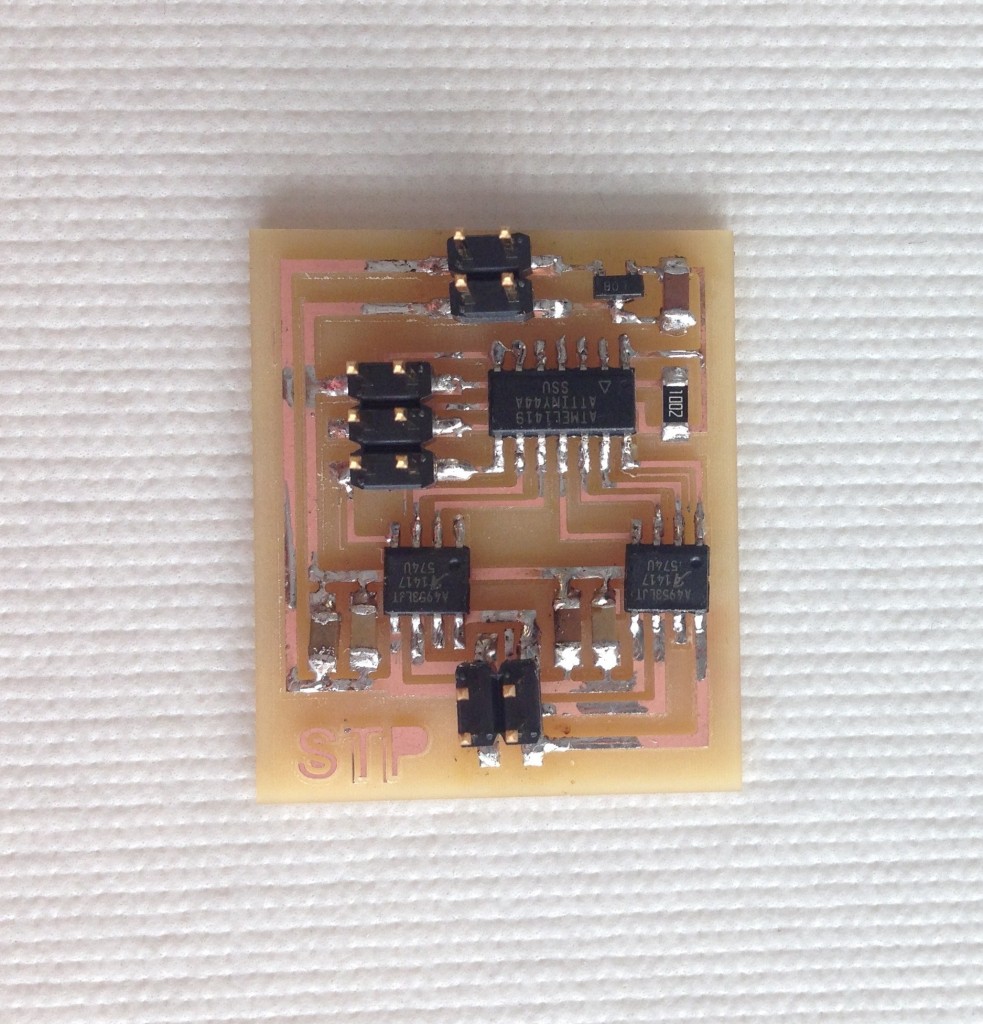
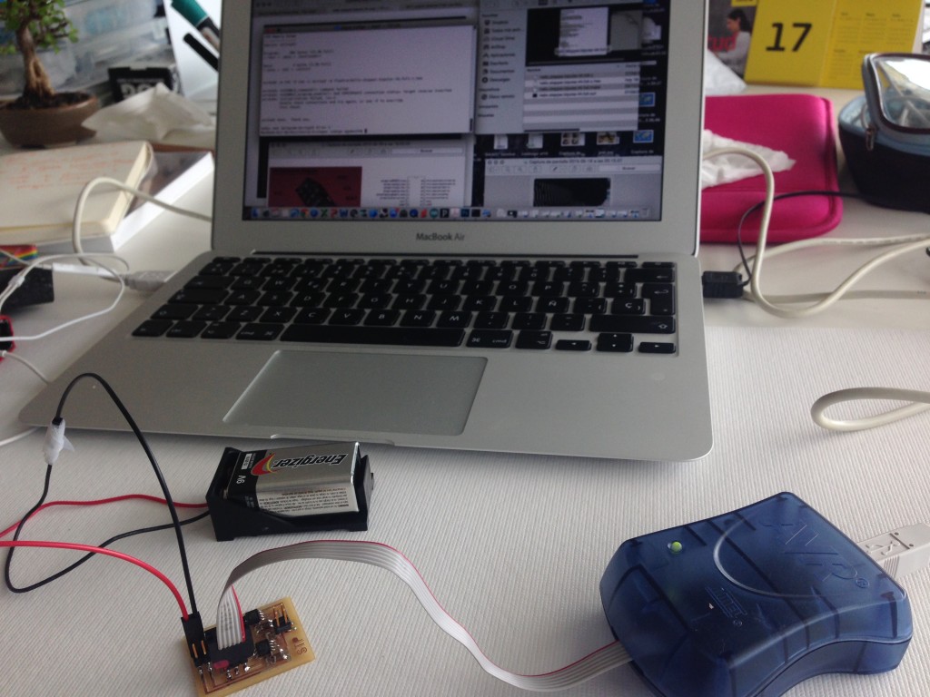
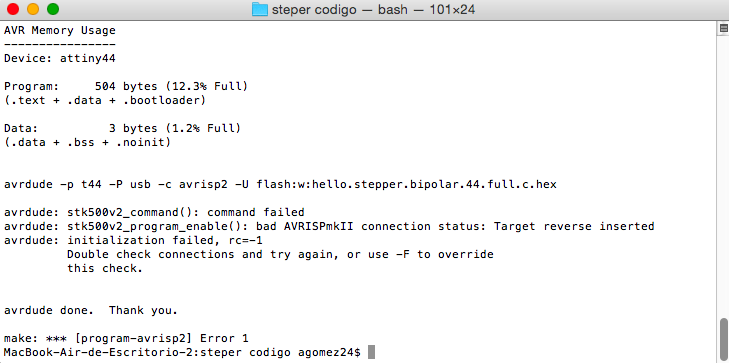
After testing and trying to upload the code by the terminal, I could not programm the board, I unsold some of the components but it did not work. As I am using the servo drive for my final project I decided to make a hello servo board from the archives.
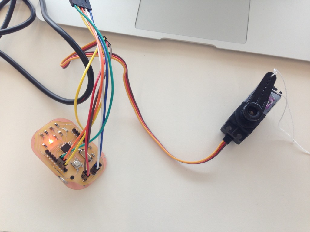
2, SERVO MOTOR DEVICE
For this board I could not make it work due to a problem with the power or soldering. The board does not allow to upload the code either.
I follow the same instructions by the terminal and also with arduino bootloader. It did not work due tu a problem with the solder, I tried to fix it without success. The I made another one and the same happened. After three attempts I decided to try with other device.
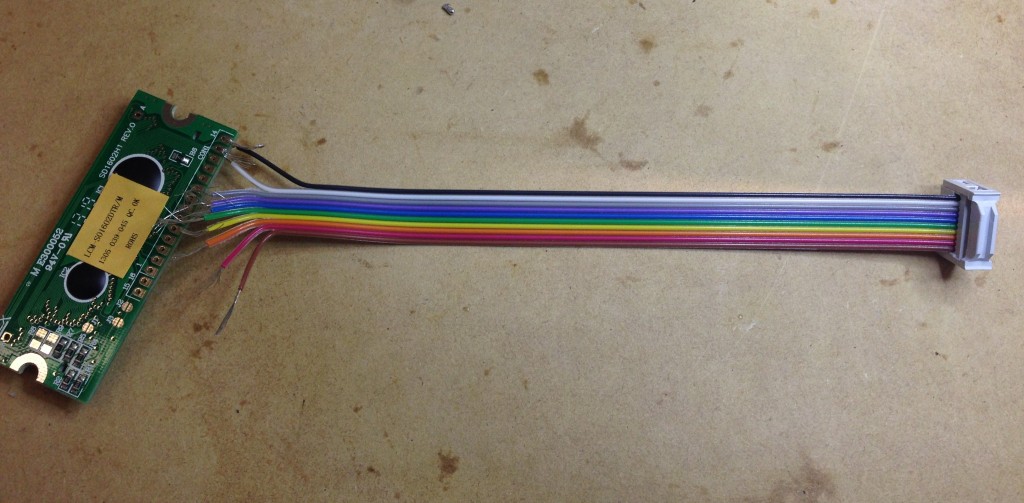
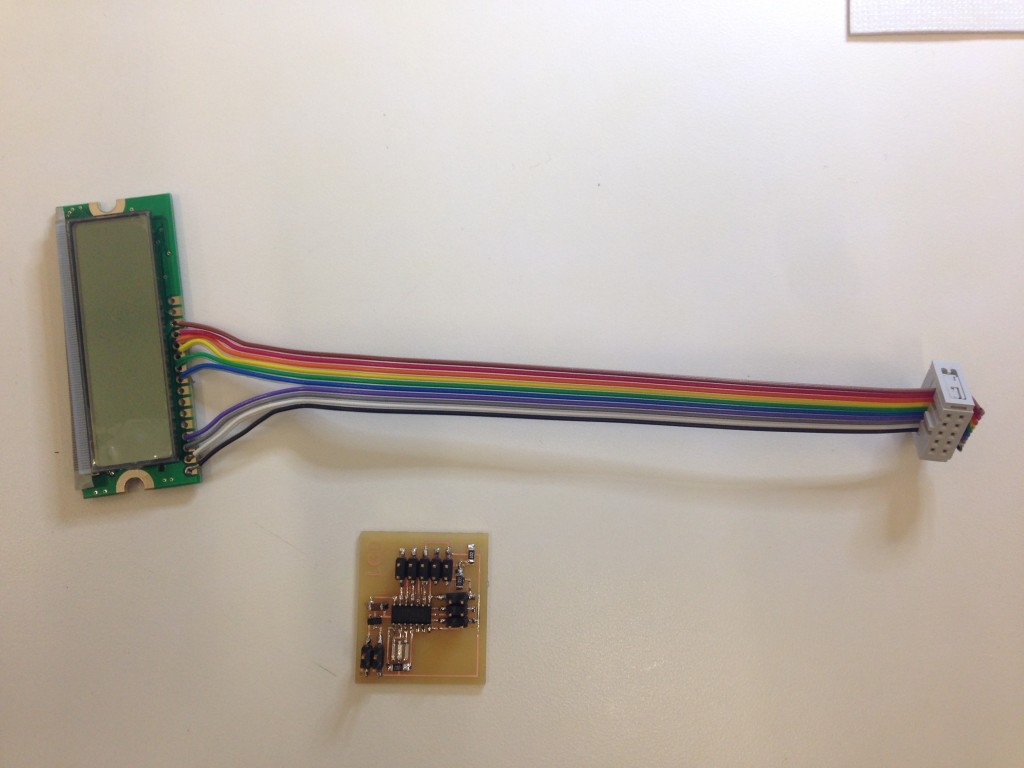
3. LCD DEVICE
I made the board using the hello.lcd files and also I had to solder the cable to the LCD display. I follow the instructions on the datasheet (pins 1.4 and 9 to 14).
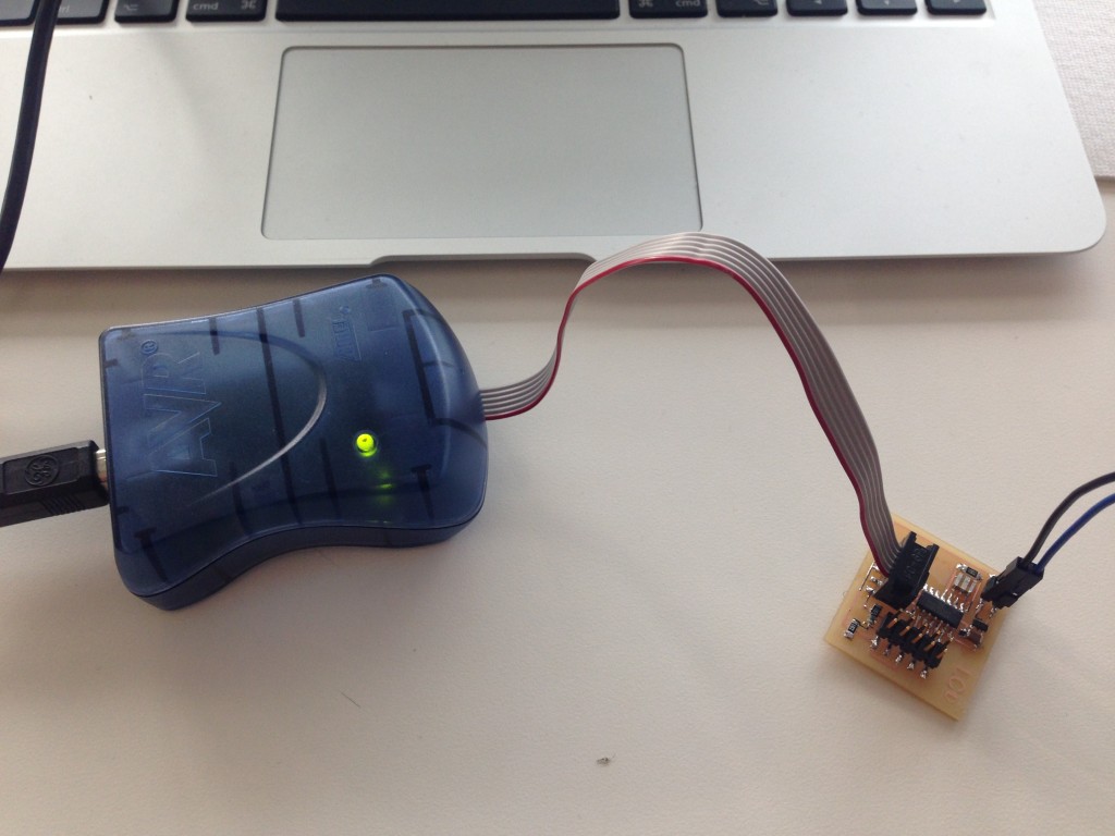
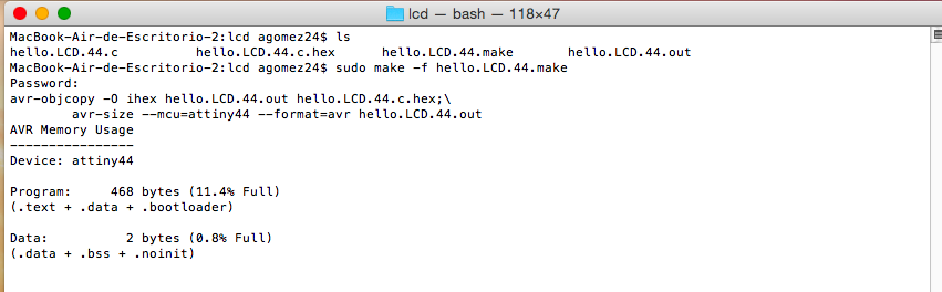
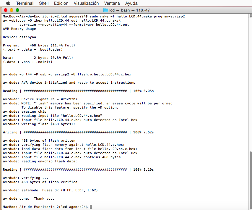
At the terminal I follow the instructions with sudo make -f and upload the code.
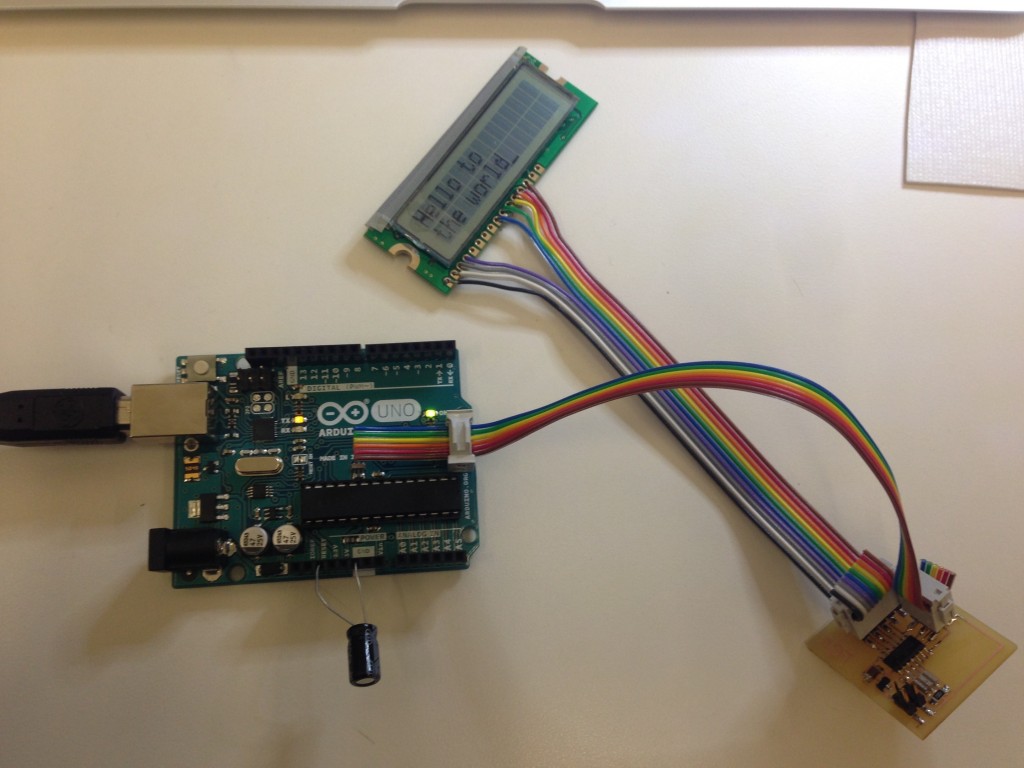
After programming the board I tried Arduino IDE to show some text in the LCD. With several attempts I could not make the code function with my LCD. Unfortunatelly, usind Arduino IDE as a platform for the LCD device imply that I have to change all the code due to the configuration of the pins on the Arduino Uno and the LCD.
In the final project I was going to need to move a motor so I insist in the motor driver. For the machines assignment I experiment with my team the use of an easy driver to move the motor and in the final project I made a microcontroller and I move a servo motor to move my acoustic panel. Here an image of the connections.