W. 10 measure something: add a sensor to a microcontroller board and read it
BOARD + SENSOR + INFORMATION
This week I wanted to work with two kind of sensors; light and sound. I am building an acoustic panel for my final project so I will need a sound sensor for input and a light or movement sensor for output.
First I needed to understand how a sensor works, so I took a built sensor and practice programming it. (see down below my results with the RGB adafruit sensor)
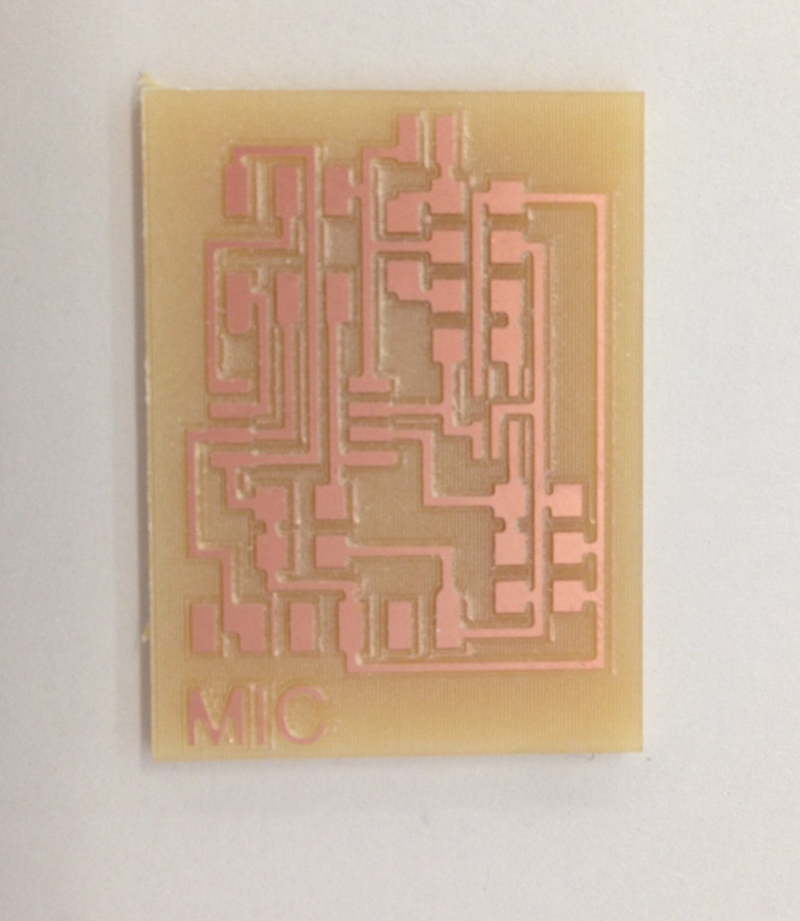
1. SOUND SENSOR (MIC)
After understanding the use of the RGB sensor I a MIC or sound sensor that can be used in my final project.
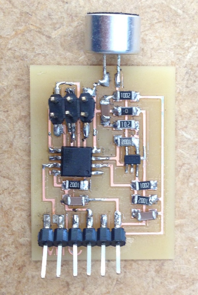
I used the hello.mic.45.cad from fab academy archive. Here the documents board, components.
I will need:
- 1 attiny 45v
- 10 10k Ohms Resistors
- 1 1k Ohms Resistor
- 1 0k Ohms Resistor
- 2 1uf Capacitors
- 1 0.1uf Capacitor
- 1 1×6 jumper jack
- 1 2×3 jumper jack
- 1 sensor Photodarlington npn clr Plcc-2
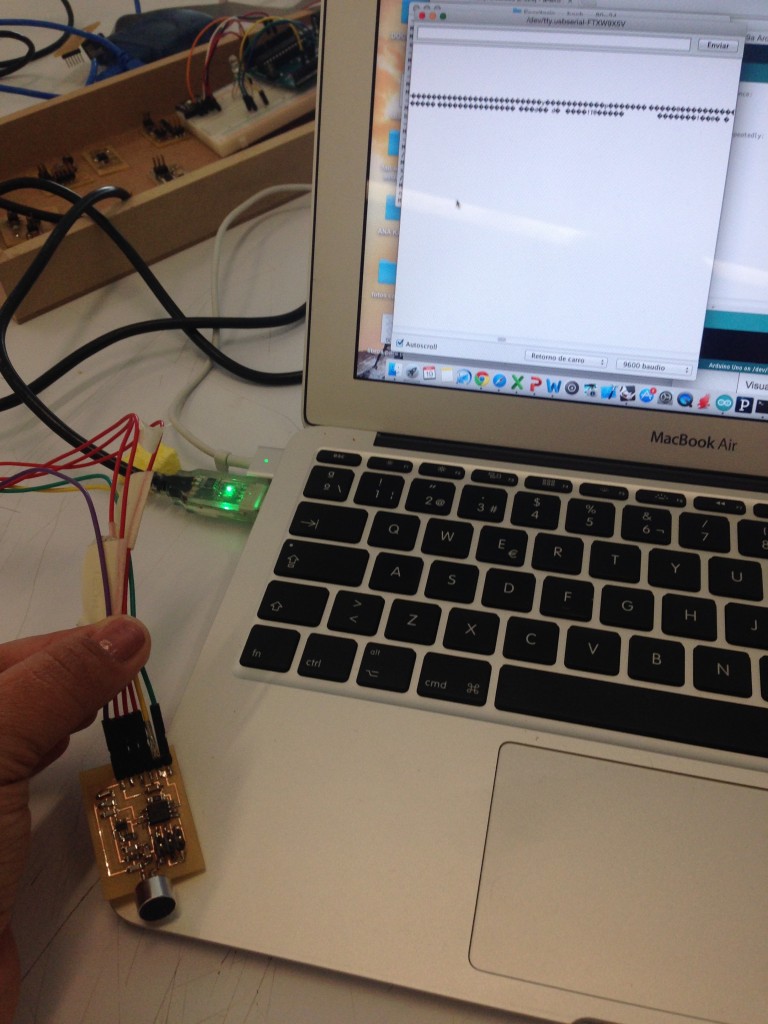
Using an AVrisp2 to program the Attiny 45 in the terminal I charge the code to the mic as follows:
- cd .. (charge the folder with the archives)
- sudo make -f (name of document)
- sudo make -f (name of document) program-usbtiny
//////////////////////
- MacBook-Air-de-Escritorio-2:~ agomez24$ cd /Users/agomez24/Desktop/codigos/sonido
- MacBook-Air-de-Escritorio-2:sonido agomez24$ sudo make -f hello.mic.45.make program-usbtiny
- Password:
- avr-objcopy -O ihex hello.mic.45.out hello.mic.45.c.hex;\
- avr-size --mcu=attiny45 --format=avr hello.mic.45.out
- AVR Memory Usage
- ----------------
- Device: attiny45
- Program: 560 bytes (13.7% Full)
- (.text + .data + .bootloader)
- Data: 201 bytes (78.5% Full)
- (.data + .bss + .noinit)
- avrdude -p t45 -P usb -c usbtiny -U flash:w:hello.mic.45.c.hex
- avrdude: AVR device initialized and ready to accept instructions
- Reading | ################################################## | 100% 0.00s
- avrdude: Device signature = 0x1e9206
- avrdude: NOTE: "flash" memory has been specified, an erase cycle will be performed
- To disable this feature, specify the -D option.
- avrdude: erasing chip
- avrdude: reading input file "hello.mic.45.c.hex"
- avrdude: input file hello.mic.45.c.hex auto detected as Intel Hex
- avrdude: writing flash (560 bytes):
- Writing | ################################################## | 100% 0.58s
- avrdude: 560 bytes of flash written
- avrdude: verifying flash memory against hello.mic.45.c.hex:
- avrdude: load data flash data from input file hello.mic.45.c.hex:
- avrdude: input file hello.mic.45.c.hex auto detected as Intel Hex
- avrdude: input file hello.mic.45.c.hex contains 560 bytes
- avrdude: reading on-chip flash data:
- Reading | ################################################## | 100% 0.68s
- avrdude: verifying ...
- avrdude: 560 bytes of flash verified
- avrdude: safemode: Fuses OK (H:FF, E:DF, L:62)
- avrdude done. Thank you.
- MacBook-Air-de-Escritorio-2:sonido agomez24$
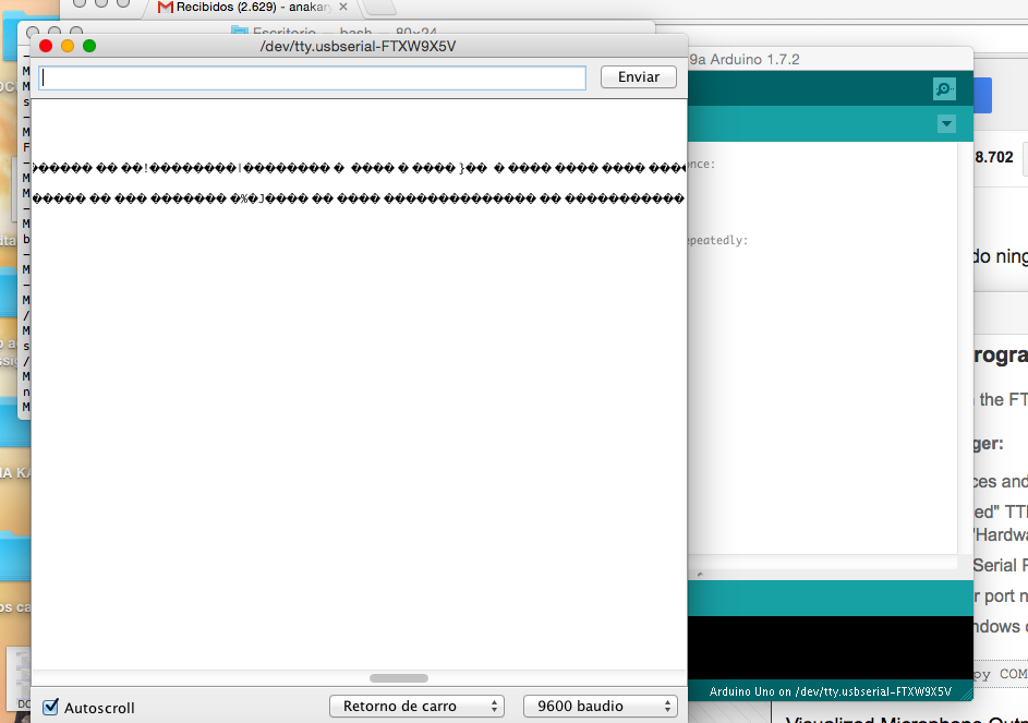
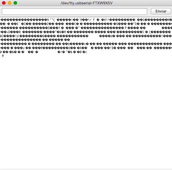
An then using arduino’s monitor serie and selecting Attiny 45 as the microprocessor, and the port I received the following:
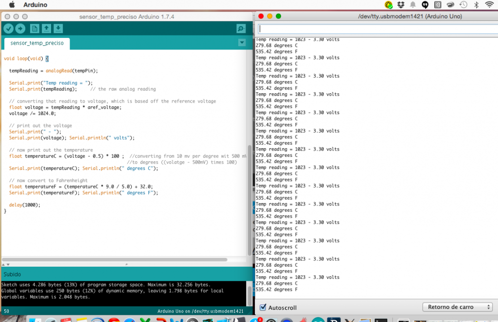
2. TEMP SENSOR
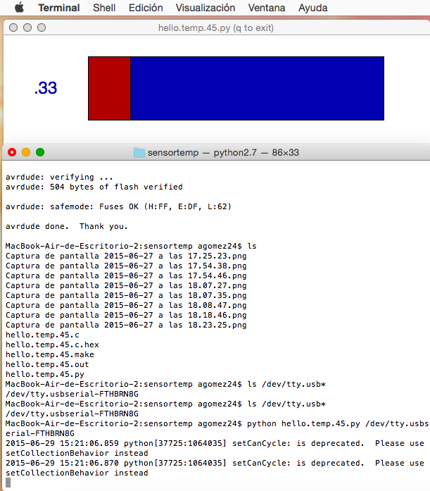
I use the hello temp sensor files to make another input device.
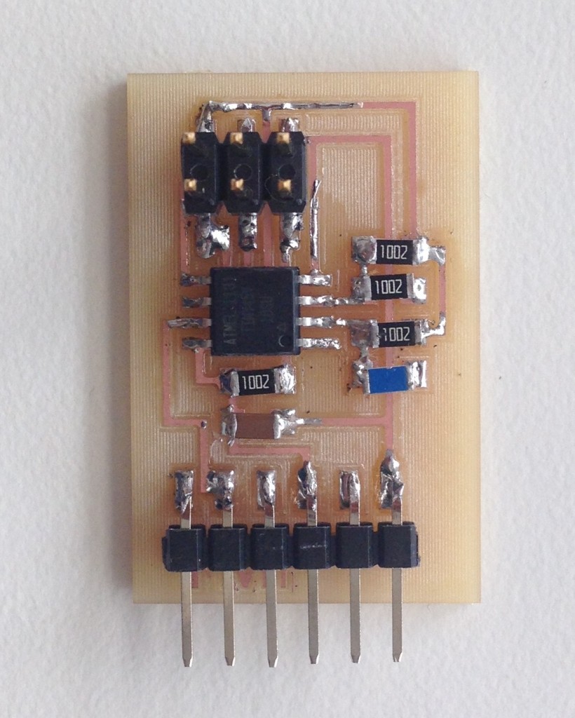
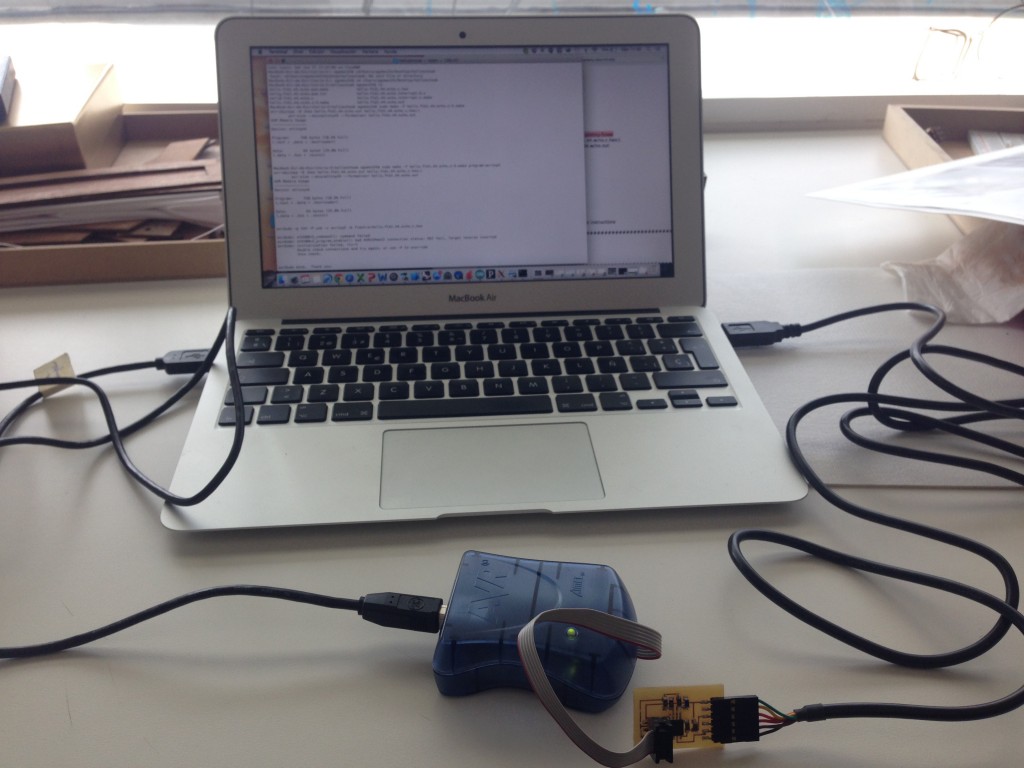
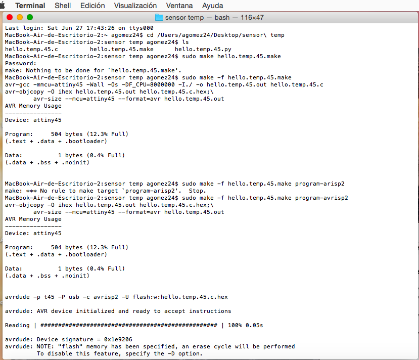
After milling and soldering the board I program it by the terminal following the commands:
- cd (upload the directory where the downloaded files are in my computer)
- sudo make -f hello.temp.45.make
- sudo make -f hello.temp.45.make program-avrisp2
- completed…
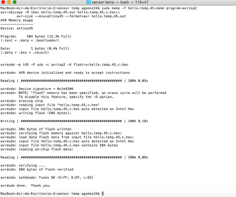
When the programming was finish I tried using python and also Arduino IDE but I did not have a good result.
3. A RGB SENSOR from adafruit
For light there is a sensor for adafruit color and light sensor TCS34725.
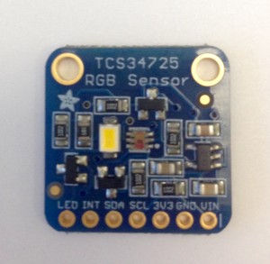
The Color and light sensor TCS34725 has the following components:
- 5 1oK Resistors
- 1 TBD Resistor
- 1 1uf Capacitor
- 1 0.1uf Capacitor
- 1 10uf Capacitors
- 1 Led 45-21/LK2C
- 1 connector (1×7)
- 3 NWVIDE BSS138 Mosfet
- 1 RT9193 VREG_SOFT23-5 Regulator
- 1 Sensor TCS34725 (light)
- 1 Sensor TEMP SENSOR RTD 1.0K OHM 1206
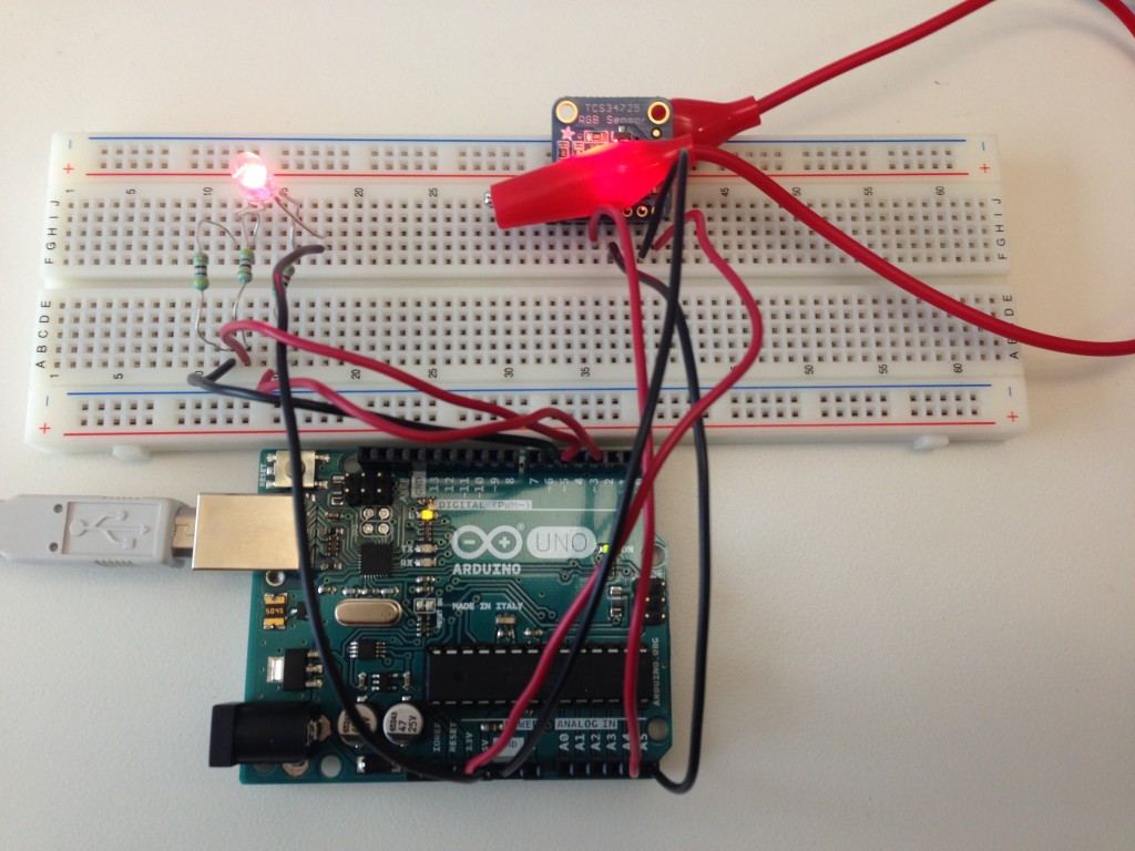
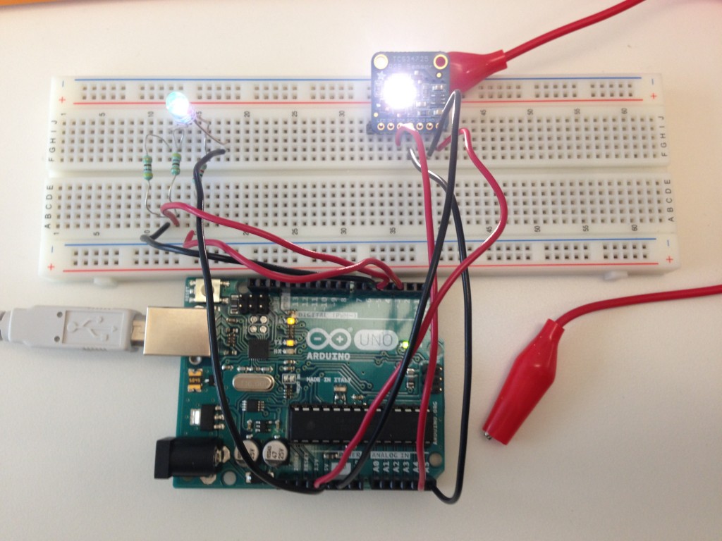
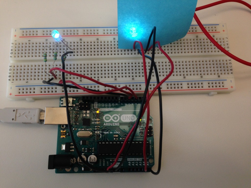
I used and Arduino UNO as a processor. I connected the sensor using wires as follows:
- GND to GND (Arduino UNO to Sensor)
- 5v to VIN (Arduiono UNO to Sensor)
- SDA to SDA ( Arduino Analog 4 to Sensor)
- SCL to SCL (Arduino Analog 5 to Sensor)
After that I connected the Arduino+Sensor to my usb port, and using Arduino UNO and the library from Adafruit for this sensor It was really easy to use.
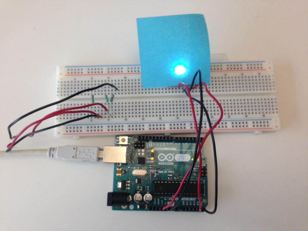
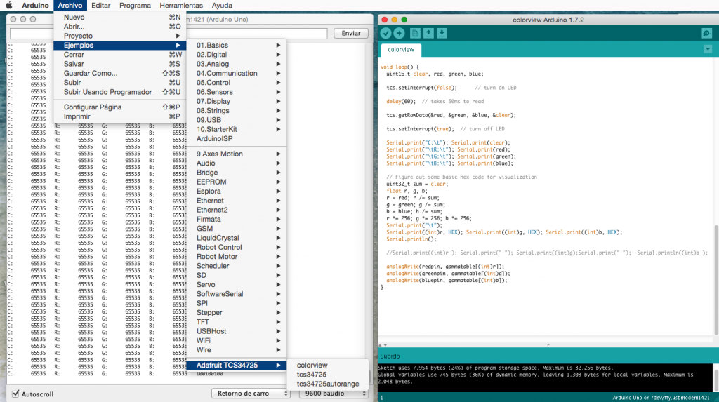
For output I wanted to use Processing, so it was really easy, just adjusting the port number (the same used in Arduino IDE for the Arduino UNO) and then with the colorview I had an exact code for the object near the sensor.
I wanted also the use an extra output, connecting an RGB Led to the board with some resistors (1x 1K Ohm resistor and 2x 499K resistor)