As I made for the input, I developed this activity as a beginner; the hello that I selected finally is the one for RGB, because I will use the changes of color for my final project.
To program my board I used Arduino as ISP, because the language is very “friendly” for me that I’m starting, and thinking about my final project maybe for me will be better ti use the Arduino IDE: I have to program a led that changes color in association with a letter, a number or a word, and changing from a color to another with degradation to the white.
The first step is to connect the board correctly to de pins! ( I still making some errors with “miso” and “mosi”!!!)
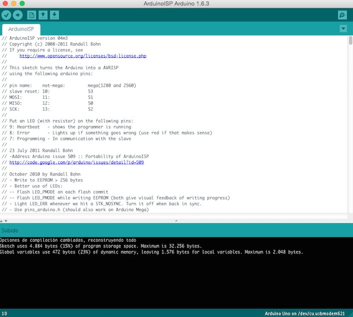
Then I did the bootloader using Arduino as ISP;
remember to select correctly your microprocessor
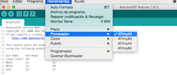
the clock
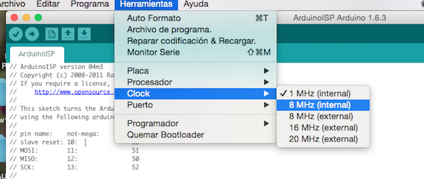
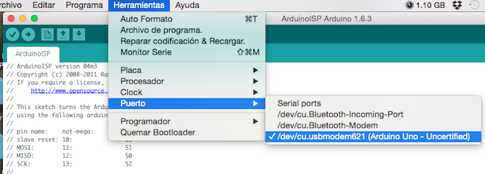
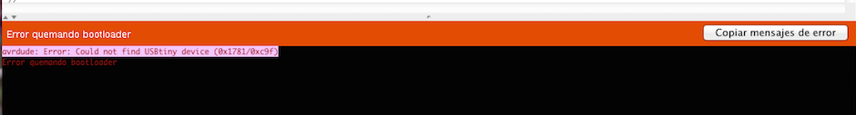
and your port too, because at first I had this error and It was because the port was not working … and I was not understanding which was the error!
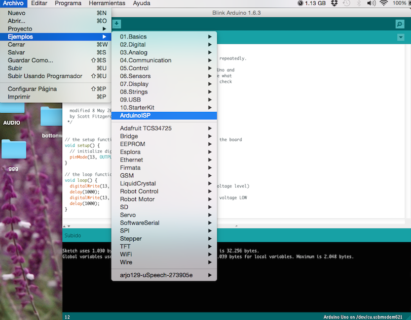
after the boot loader completed I’m ready to run a code
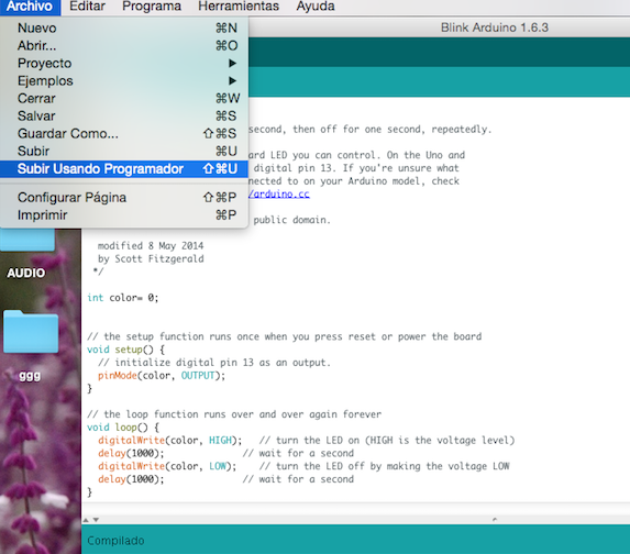
I used the “BLINK” from the examples of the basic library of Arduino that turn on and off a light, like I did for the activity of the week 7 and then I changed some part of the code
this is the original
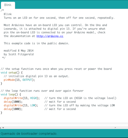
remember to run to select the option with the programmer
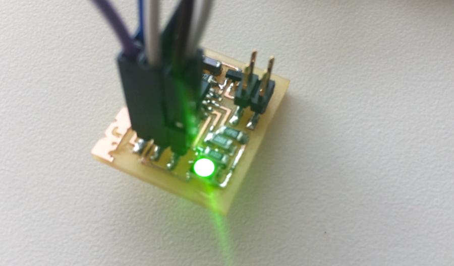
and this is the change that I did
// Blink modified Daniela Frogheri – Fab Academy 2015 int G = O; // the setup function runs once when you press reset or power the board void setup() { pinMode(G, OUTPUT); } // the loop function runs over and over again forever void loop() { digitalWrite(G, HIGH); // turn the LED on (HIGH is the voltage level) delay(1000); // wait for a second }
the led that are turning off and out is the green one, connected with the pin 0
the I add all the others led and I did the same for each one
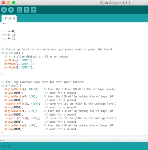
this is my code
- // Blink modified Daniela Frogheri - Fab Academy 2015
- int R = 1; // I selected the pins looking the schetch of the hello board
- int G = 0;
- int B = 2;
- // the setup function runs once when you press reset or power the board
- void setup() {
- pinMode(R, OUTPUT);
- pinMode(G, OUTPUT);
- pinMode(B, OUTPUT);
- }
- // the loop function runs over and over again forever
- void loop() {
- digitalWrite(R, HIGH); // turn the LED on (HIGH is the voltage level)
- delay(1000); // wait for a second
- digitalWrite(R, LOW); // turn the LED off by making the voltage LOW
- delay(1000); // wait for a second
- digitalWrite(G, HIGH); // turn the LED on (HIGH is the voltage level)
- delay(1000); // wait for a second
- digitalWrite(B, LOW); // turn the LED off by making the voltage LOW
- delay(1000); // wait for a second
- delay(1000); // wait for a second
- digitalWrite(B, LOW); // turn the LED off by making the voltage LOW
- delay(1000); // wait for a second
- }
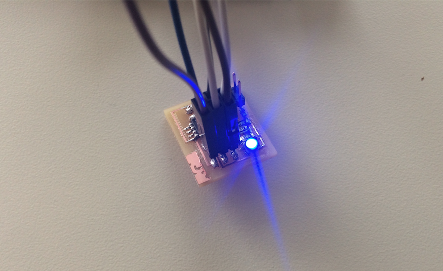
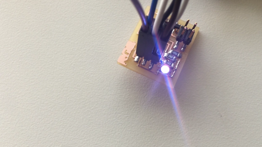
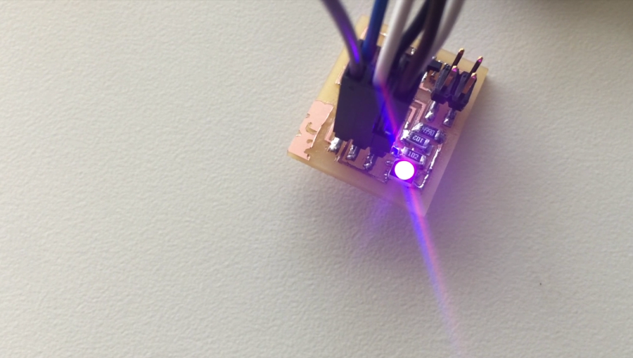
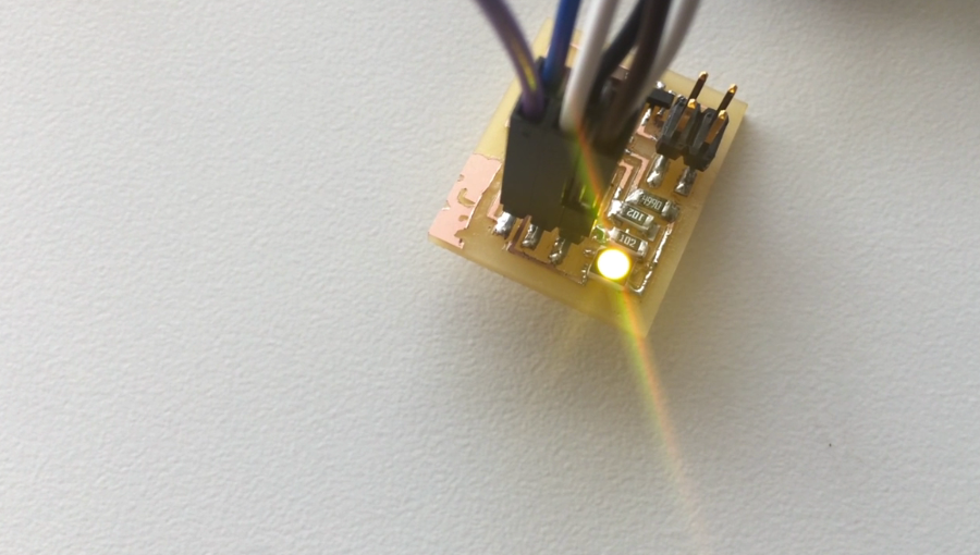
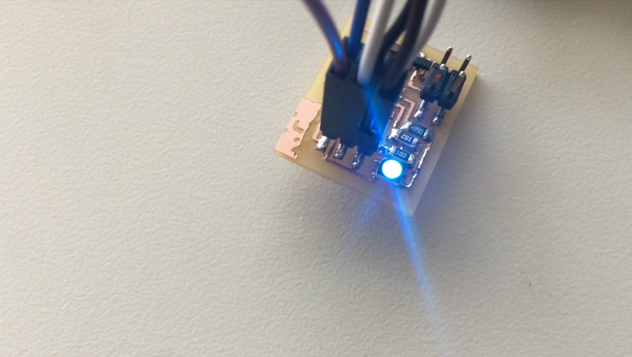
here some images to he code running …but the result is something different than I expected …. honestly I have to study more about … … I have to work a lot to program how to simulate the colors of synaesthesia!
First work: exploring the hello boards and milling the PCBs
As last week, I still working on the process to test, understand and think about input and output, and my work is in progress also because here in Monterrey we are waiting from the components that we need to complete our last PCBs.
I will reorganize soon these two assignments ( 10 & 11) , because last week I developed an activity with input and output together, at first using and testing an existent color sensor, learning how it works, and then I experimented two ways to obtain his output, one on the pc, with processing, and the other with a led, but putting all the elements in a breadboard … my experiment was simple, but it works; I started on this way because this part is new for me, but I think that maybe is the most important part to make well my project.
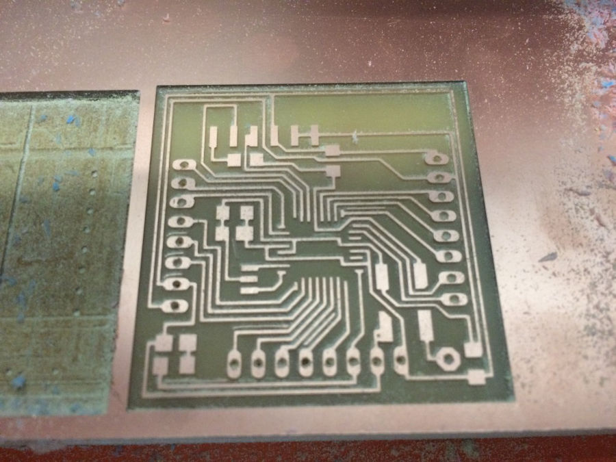
Now, I´m trying to build the input and output boards that I need for my project, and to start I selected some of the examples that we have, to study how them work, and to think about the changes that I have to do;
For now I did the boards, but I have not all the components; I hope to receive them in 3 or 4 days.
I´m working with synesthesia, and for this, I want to use colors, light, sounds but I’m interested also on temperature and movement.
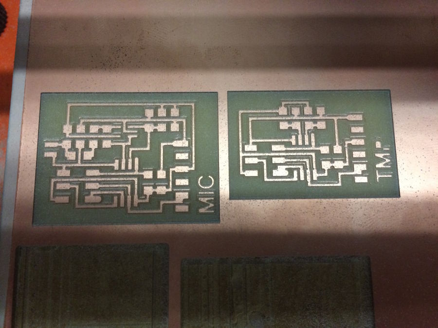
Input
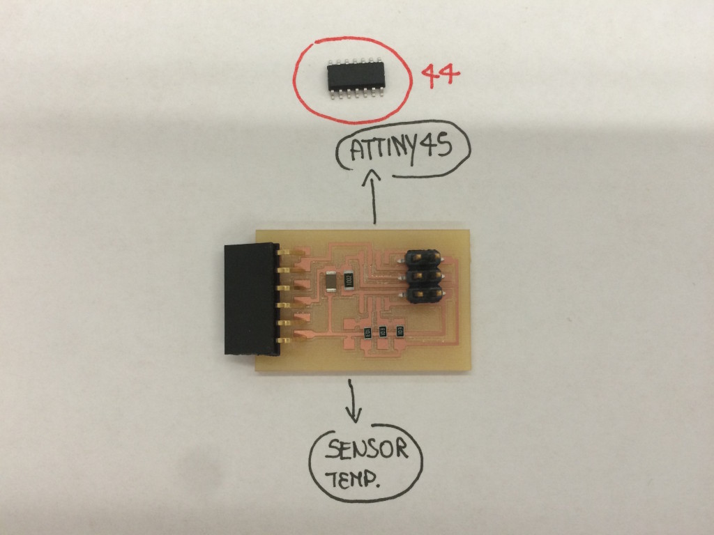
For the input, for now I selected the sensor of temperature and the microphone
but I want to use the color sensor too … while the components are coming, here I’m starting to prepare my boards and studying the components.
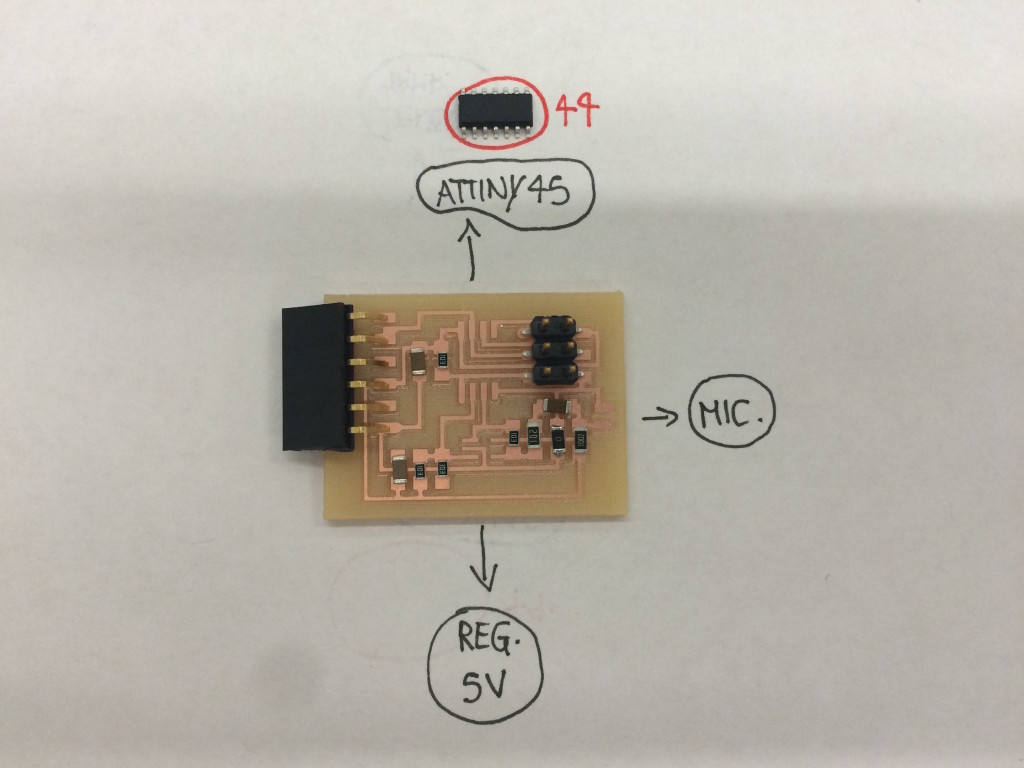
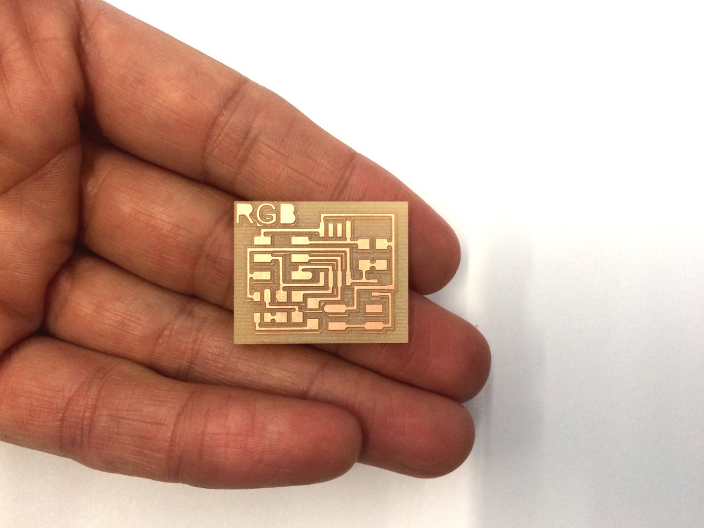
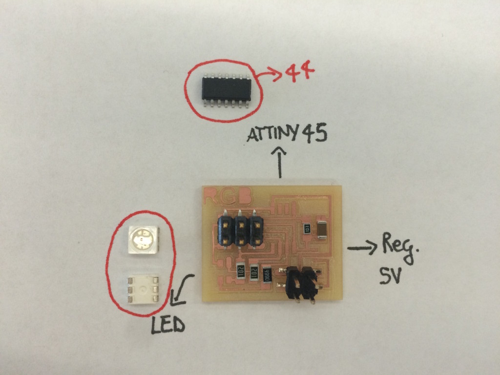
Output
For the output, I selected the RGB, but I´m planning to use a motor too; this is that I have for now.
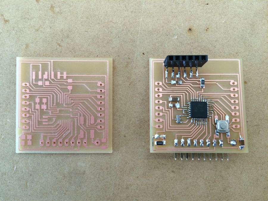
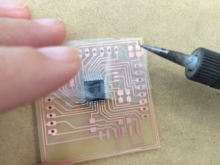
The Fab Kit
Another thing that we did in our fab lab these days is start to build the Fab Kit; last week I experimented by using an Arduino, but now finally we have the microcontroller for the Fab Kit; As you can see, for now we are using the version 0.4, with the instructios of Massimo Menichinelli, but we hope to be able to build soon our version;
http://fabacademy.org/archives/2015/doc/fabkit-0.4.html
Finally … I’m are improving weldings! the atmega 328p is very small … and we found some of the components only in 0805 or in 0603 … we changed also some parameters in our Monofab SRM 20, because the process was really very very slow … and now we are able to build our the Fab Kit PCB in 2 hours and the smallest in less than one hour
Files: