AUTOMATIC 3D CHICHA SCANNER
STEP 18: PROJECT DEVELOPMENT
OBJECTIVE
- Create an automatic 3D "Chicha" scanner
- Develop an witty solution with a simple (maybe not that artsy) design
Note: I initally wanted to develop a foldable 3D Printer-Scanner, but due to my lack of formal knowledge in design and electronics, this project is for the long run.
JUSTIFICATION
- Increase the precision and speed of the Milk scanner technique, through a cheap, accesible and easy way.
PROCESS
STRUCTURE
- Made of 6mm and 3mm thick acrylic
- 200mmx560mm
- 200mmx200mm cubes (2)
- Floors (3)
- Holes for connecting each material
What has not worked
BRAINSTORMING PATHS
- I was definetely going to use a webcam for taking pictures of the layers. On the other hand, I had four options for regulating the water flow before I got into more detail with my design and developing the electronics:
1) Using a water depth sensor for measuring the increasement of Chicha. I did not choose it, because it would have required many current flow sensor (water sensor) that would have required a lot of material.
Here, you can look at my water sensor.
2) Using a ultrasound sensor for measuring the increasement of Chicha. I did not choose it, because an ultrasound sensor is not accurate and my machine needs to be exact for working and actually meeting my goal.
3) Using a electrovalve for releasing and keeping the Chicha. I did not choose this option, because it was expensive, not easily accesible, unnecessarily complex and required more a lot of material and time as an electrovalve needs its own board with relays and transistors.
Here, you can look at my electrovalve.
4) Using a plastic tap and a servomotor and joining them with belts. I did not choose this option, because it did not allow the servmotor axis to move.
Here, you can look at my plastic tap and servomotor joined by belts.
What has worked
5) Using a plastic tap and a servomotor, by joining them with a nilon piece, for controlling the flow of Chicha. I chose this option, because it was small, accurate, cheap, accesible, structurally simple and seemed witty-maker.
What tasks have been completed, and what tasks remain?
Completed:
Design
Electronics
Programming
Assembly
Remaining:
Developing 3D Scanning software where you just upload pictures for getting a 3D Picture without the need of a design software like Rhinoceros
DESIGN
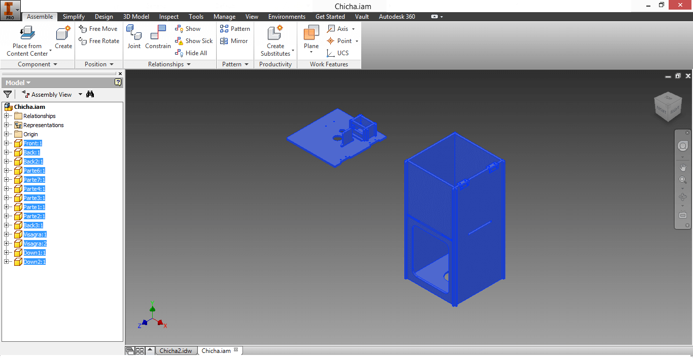
1. I designed the pieces of my machine in Inventor.
2. I assembled the pieces using 'Assembly' to make sure I did not have trouble with enssambles.
Note: You can download my Assembly Here.
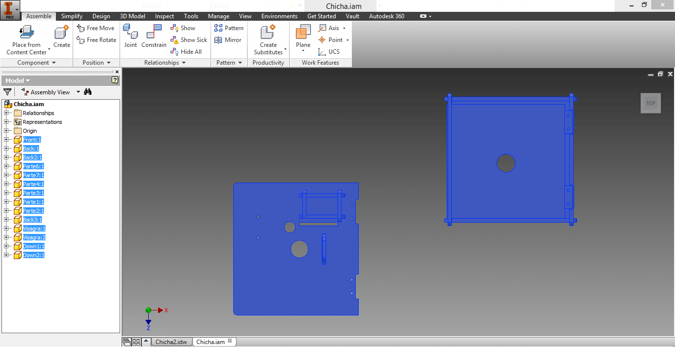
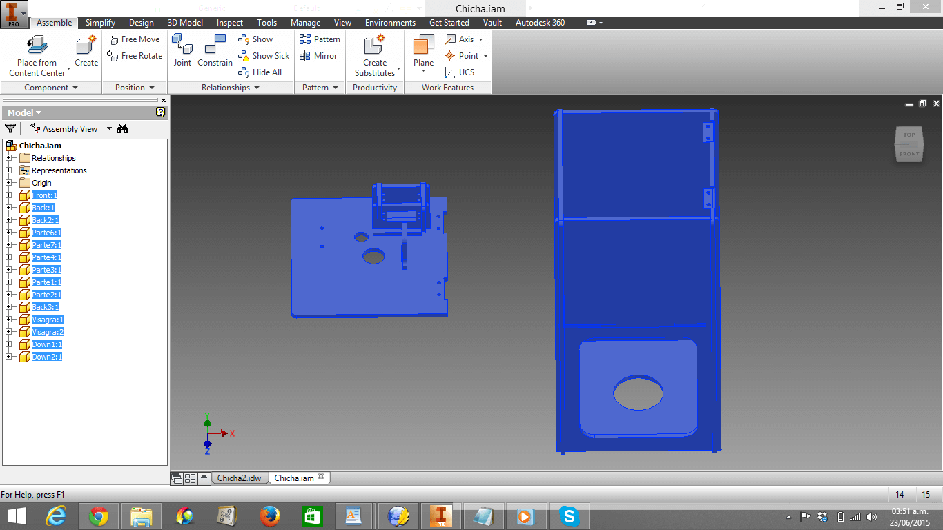
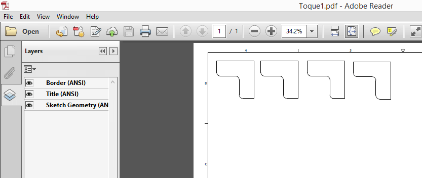
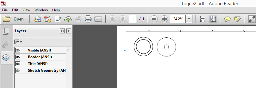
3. I opened them in idw format.Then I cutted them in pdf
Note: You can download my pieces in idw. format Here and pdf format Here.

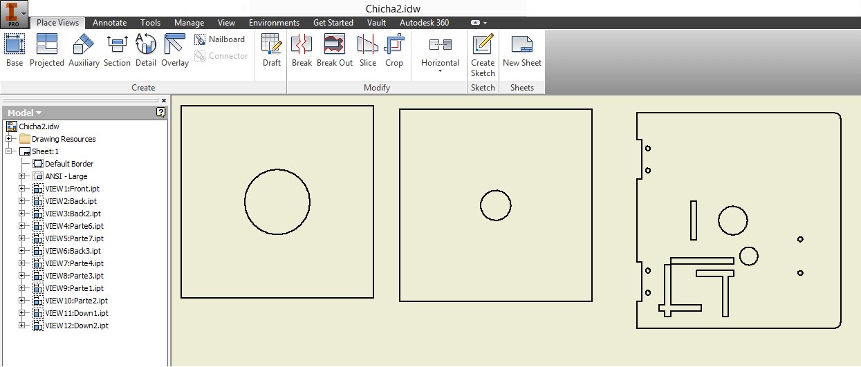
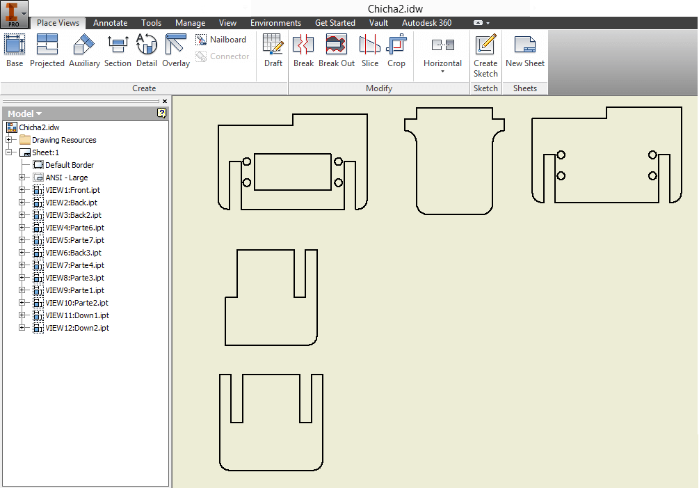
4. I should mention, that later on, after building the pieces, I made adjustments. Therefore, I designed new pieces in Inventor and opened them in idw. format and exported them in pdf. format for cutting them in the Laser machine.
Note: You can download my first pdf Here and my second pdf Here.
ELECTRONICS
1. I milled the Fabduino three times using the design provided by Fab TECSUP thanks to Roberto Delgado and Jose de los Ríos' editions. The first two times I was not succesful, due to the fact that solding the ATMega pins was very hard for me. You can download the Fabduino's (1/64 mill) interior traces Here and the outer traces (1/32 mill) Here.
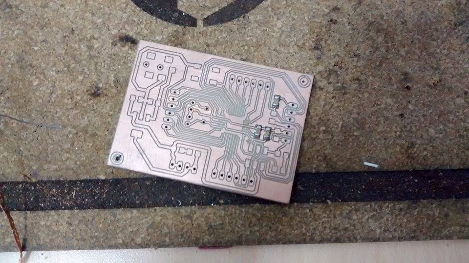
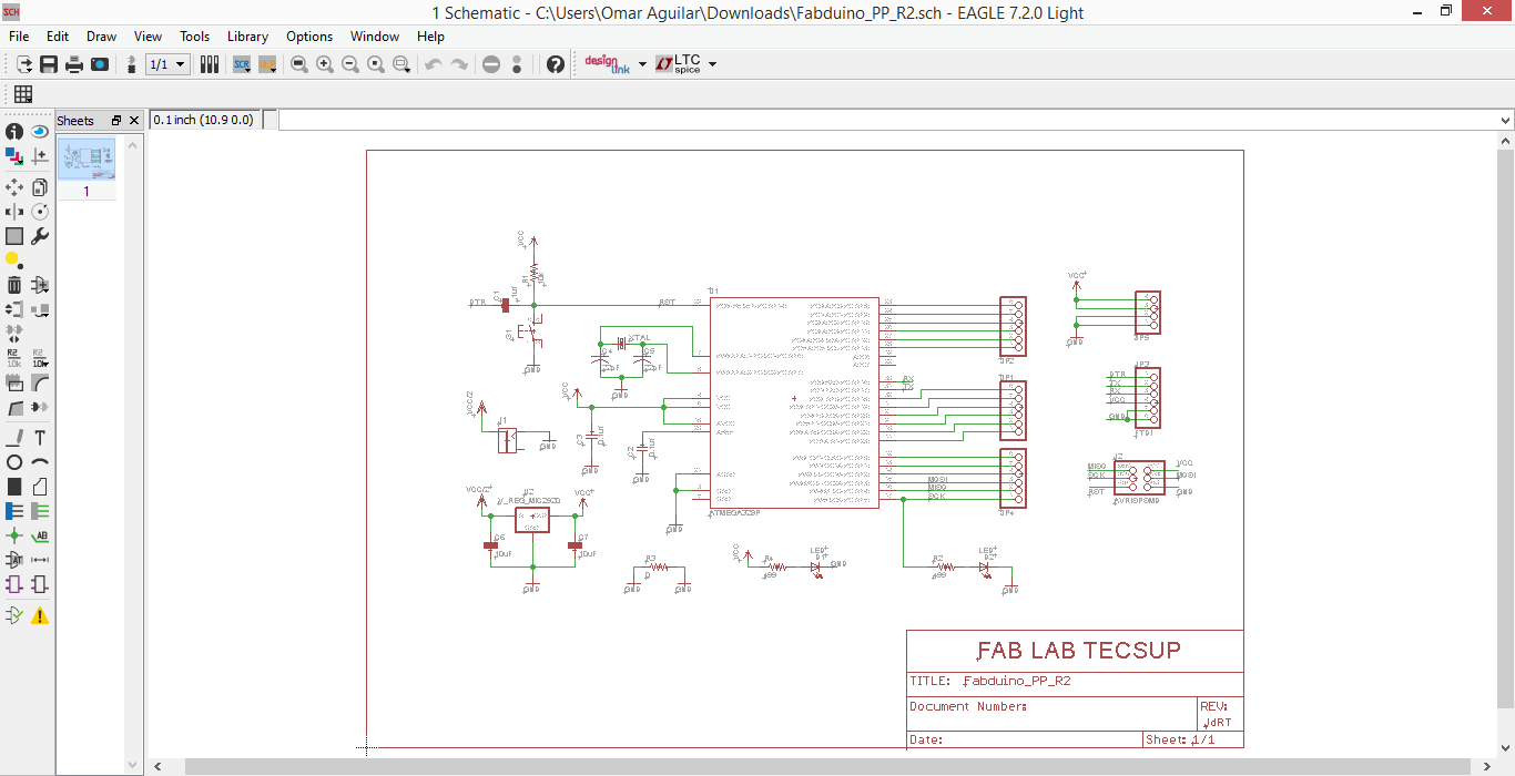
2. I downloaded the Fabduino Eagle archive provided by Fab TECSUP thanks to Roberto Delgado and Jose de los Ríos' editions. You can download the Fabduino's schematic Here and the Fabduino's board Here.
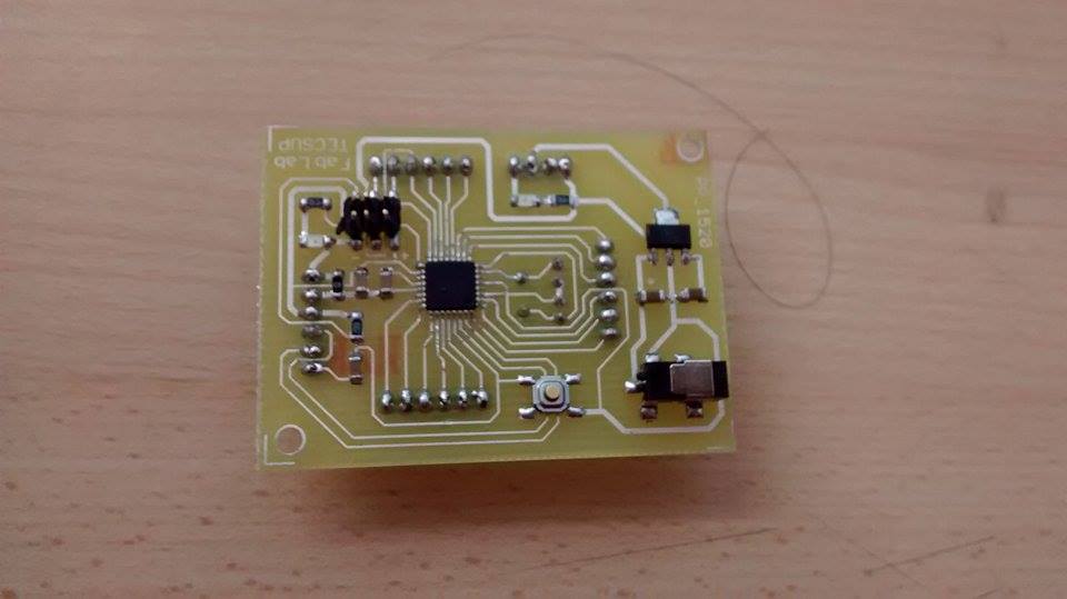
3. I solded my Fabduino using little flux this time, for not messing my board,
CHARGING FABDUINO PROGRAM
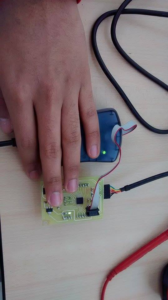
1. For programming my solded Fabduino as an Arduino, I connected it to an AVR mkii and connected the AVR mkii to my computer. It should be said that I followed the current flow rule I wrote in Week4, for connecting the pin-out with my Fabduino.
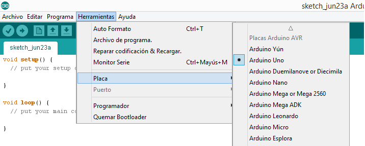
2. I clicked on Tools -> Board -> Arduino UNO
4. However, I got this message:
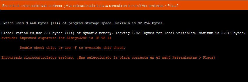
5. That's why I entered to Downloads -> arduino-1.6.1 -> hardware -> tools -> avr -> avrdude.conf
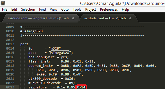
6. I opened the Sublimetext file and changed the 0F for 14.
4. I tried to burn the Bootloader, but it did not work out...
Here is the link that shows I burnt the Bootloader.
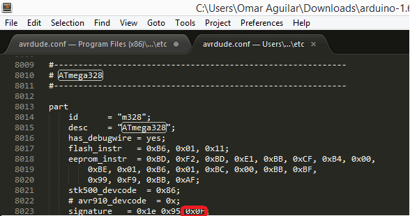
6. After burning the Bootloader, I changed the 14 for 0F again -> Tried Example -> Blink (for verfying its function).
Here is the link that shows my Fabduino working.
PROGRAMMING IN ARDUINO IDE
PROGRAMMING IN PROCESING
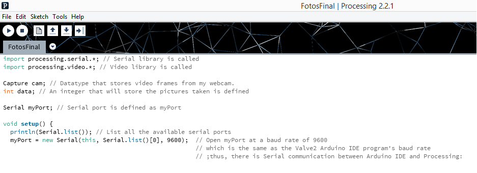
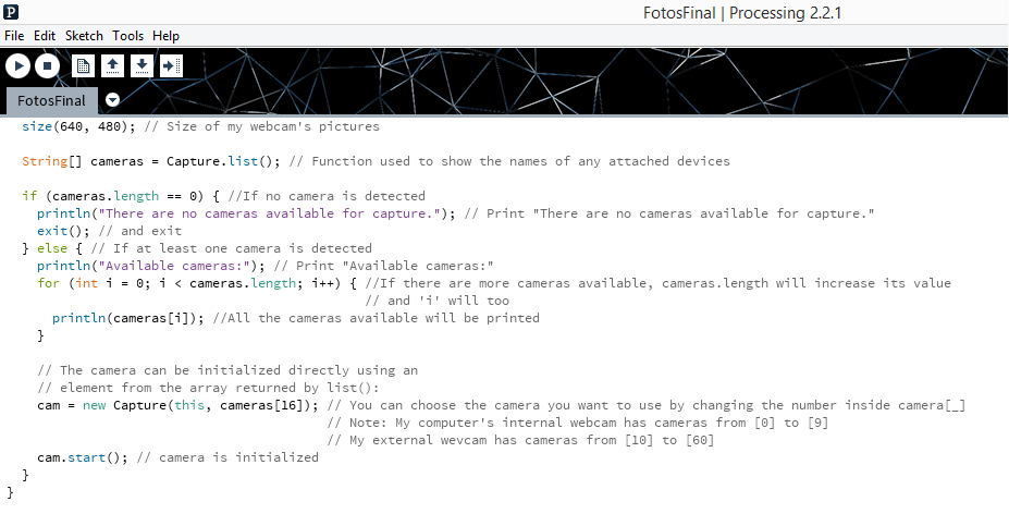
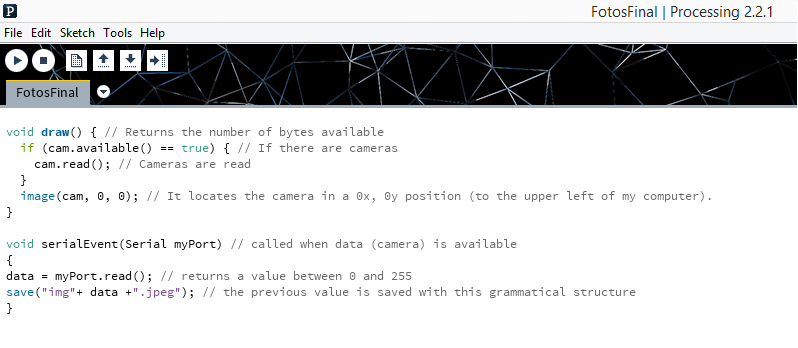
1. I used Capture, available(), serialEvent() and read() as molds for developing the program that would allow my Webcam take a picture each time one of 12 Arduino cycles was over.
You can find Capture Here, available() Here, serialEvent() Here and read() Here. Also, here you can download my Processing program, FinalFotos.
2. My Processing program with each line explained by me, is shown below.
RUN
Here, in this video, my Automatic 3D Chicha scanner is fuly working.
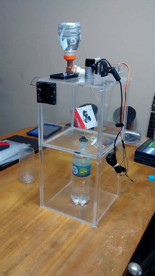
ASSEMBLY
1. After cutting all the pieces in 6mm and 3mm acrylic, I assembled the third floor using cloroform and a ruler.
2. I assembled the second and first floor with the walls (in this order). I made the assembly using cloroform and a ruler.
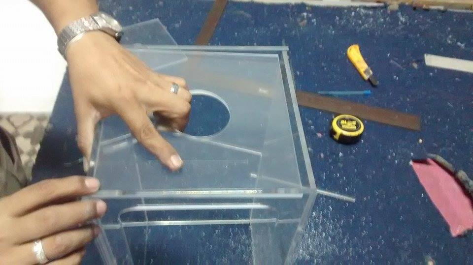
3. I made sure that the third floor was going to fit with structure when joined by hinges.
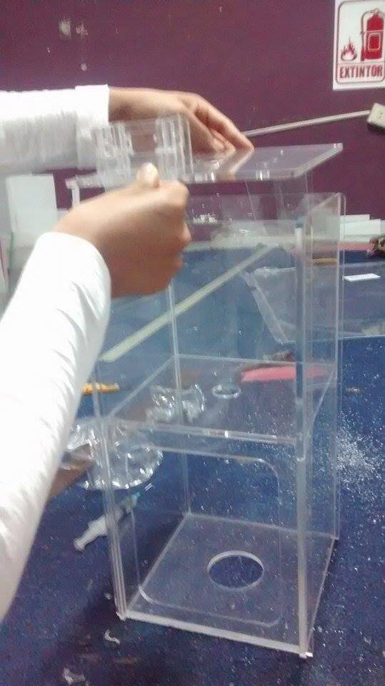
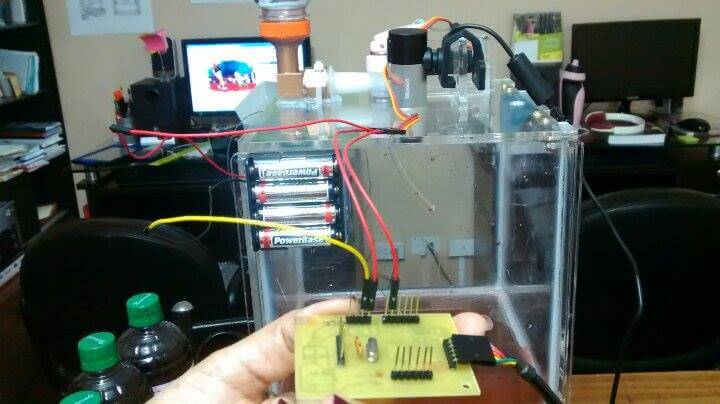
4. I put my webcam, Fabduino and Servomotor in the Third Floor. I should said that I had to break the Servomotor acrylyc case, because I forgot to put it inside, before assembly. Anyway, I pasted it with cloroform and there was no toruble.
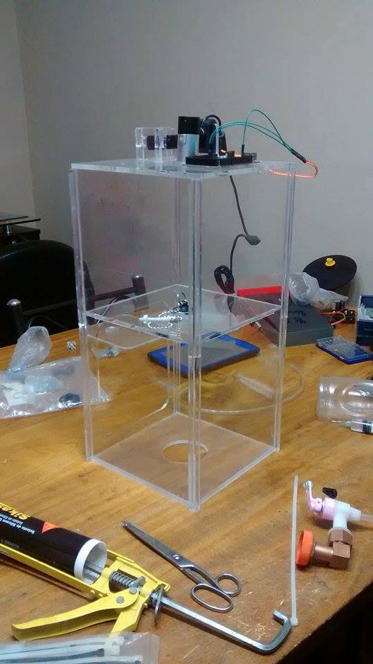
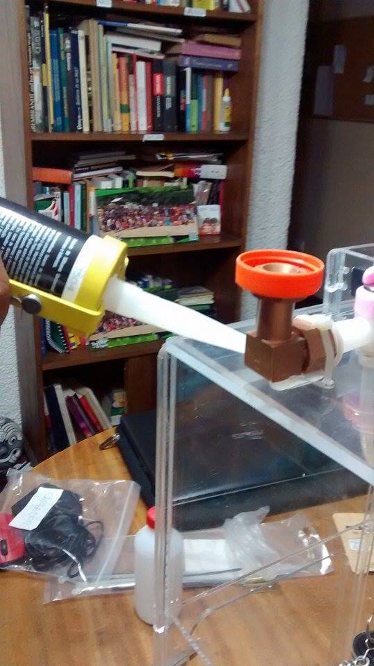
5. I tied the bronze elbow (next to my servomotor) to the Third Floor using a plastic belt. I pasted the bronze elbow with silicone.
7. I identified the VCC, GNDs and digital pin 9 of my Fabduino using its schematic. This is the result.
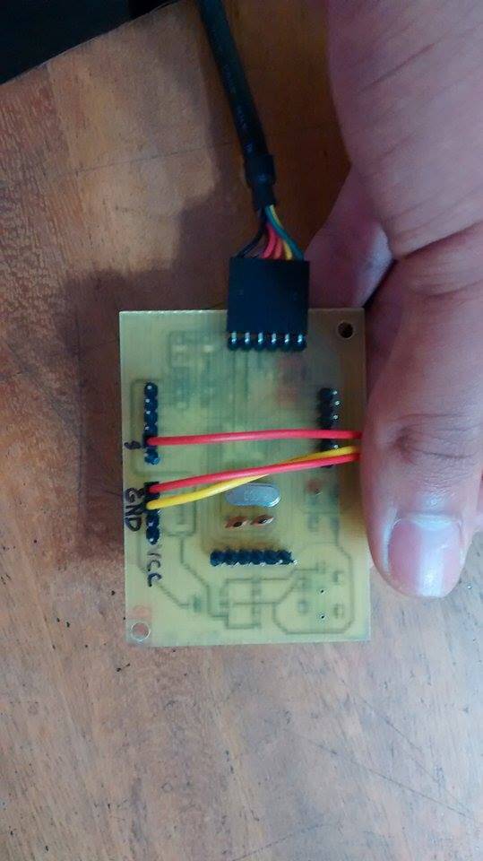
8. I connected the Servomotor's and Battery's cables to the Fabduino and the Processing did not work. Then, Eduardo Yallico told me, that as the Arduino was already feeding the Servomotor, it did not have voltage left to feed the Webcam (that's why my Laptop port was sound; it was opening anc closing). That's why I connected the Battery's VCC (red) cable to the Servomotor's VCC (red cable), the Battery's GND (black) cable and the Servomotor's GND (black) cable to the Fabduino and the Servomotor's Serial (yellow) cable to the Fabduino.
9. My project run successfully and this is how it looked.
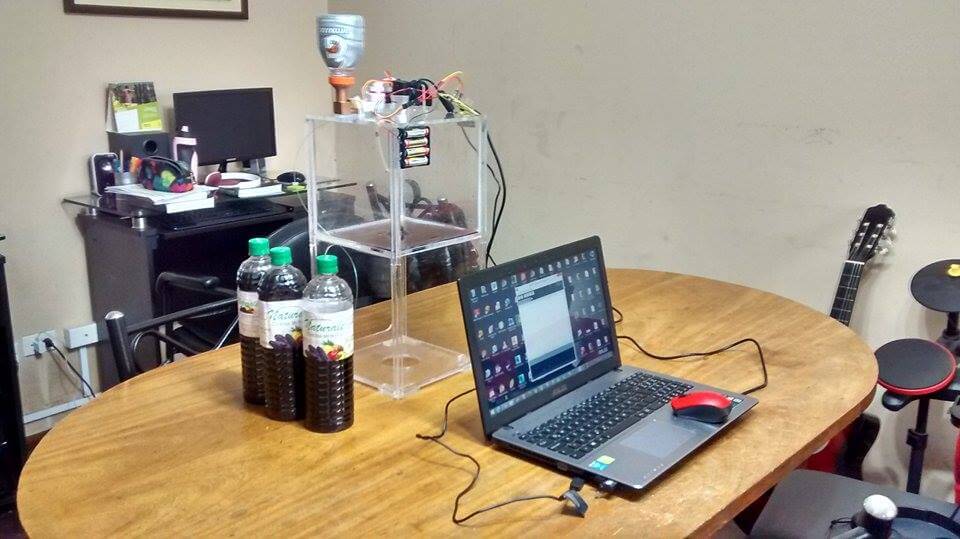
You can download my video here.
10. I scanned the top of a Christmas Sugar Pot and a Sintestchotch. I should mention, that this process allowed me to realize experimentally that a plastic tap needs to remain open for 24 seconds, for getting the liquid height to increase 1cm. Here are the results of my experimentation: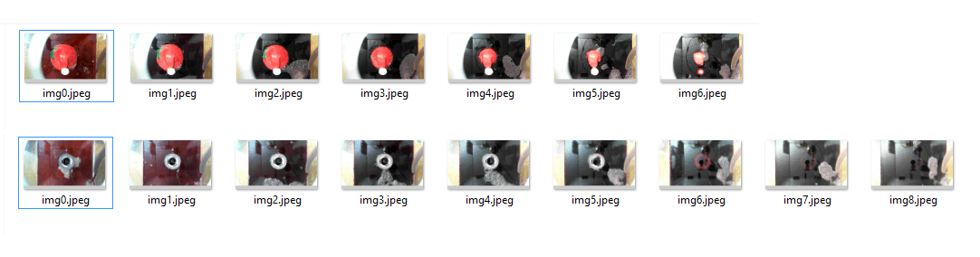
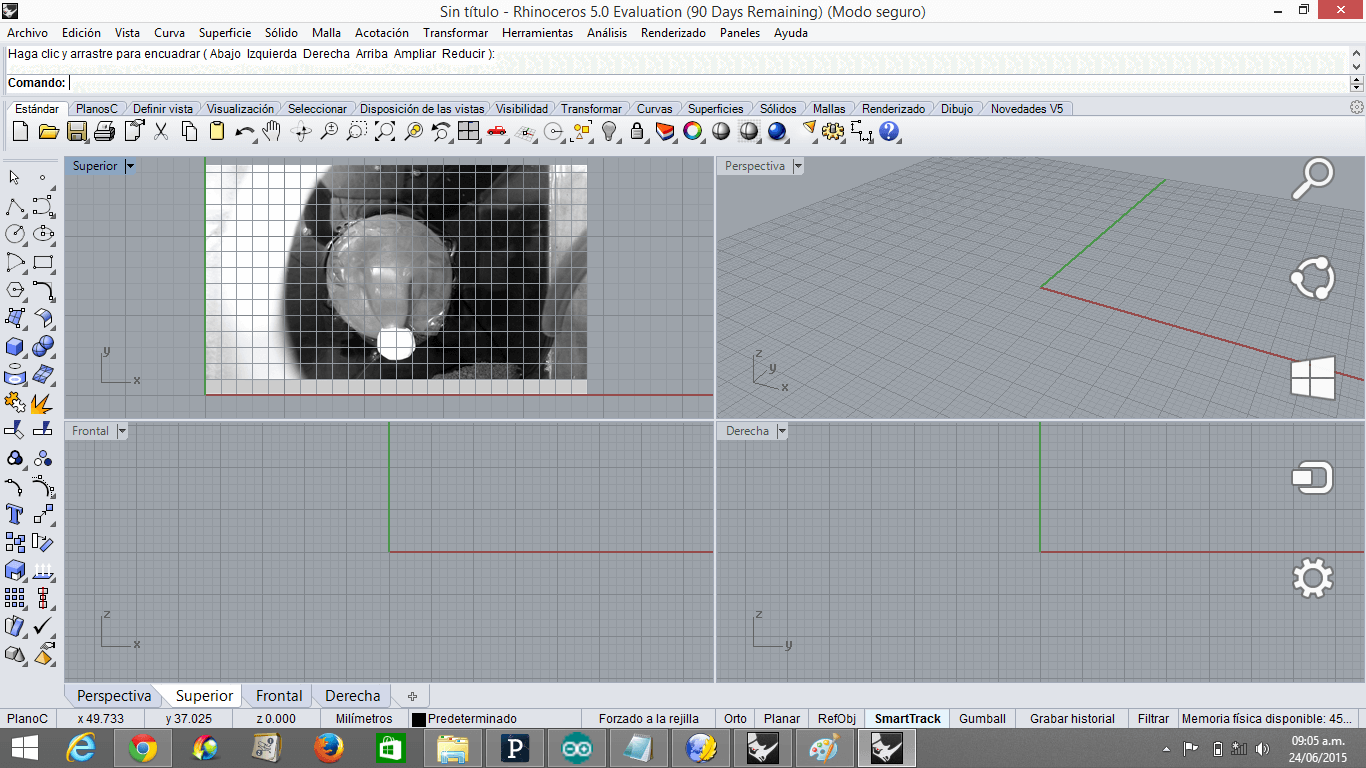
11. The previous pictures can be joined using Photoshop or Rhinoceros. This would be the next step of my project. Here is a preview
What question needs to be resolved?
Is it possible to develop a software that generates a 3D Picture of an object just by uploading the pictures of the object's layers?
What will happen when?
I will develop the software mentioned above after I finish the Fab Academy.
BILL OF MATERIALS AND FUNCTIONS
1) 180cmx120cm 6mm Acrylic: It is the structure, where all the the project is supported
2) 20cmx20cm 3mm Acrylic: It is the adjustments material for efficient exit of Chicha, once the scanning its over.
3) FTDI Cable: It allows the Fabduino to receive the Arduino IDE Program and execute the Processing program.
4) [4] 1.5V Batteries Case: It supports 4 Batteries, and have 2 cables (GND and VCC) that connect with the Arduino board and the Servomotor.
5) [4] 1.5V Batteries: They provide energy to the system.
6) Half of Gatorade bottle: It works as a funnel that allows me to pour Chicha inside my machine
7) San Luis water bottle: It receives the Chicha when the scanning process is over. It helps the cleaning process.
8) Bath cap: It closes the Second Floor and allows to control the flow of Chicha.
9) Webcam: It takes pictures of each layer
10) Plastic tap: It allows the Chicha to get or not get inside the system
11) 15 kilograms Servomotor: It initializes or resets the plastic tap
12) 5cmx4cm Bronze elbow: It allows Chicha to get into the system without the need of an extra force, but gravity.
13) Plastic belt: It supports the elbow bronze
14) 1mm Nilon: It connects the Servomotor with the Plastic tap for creating the Open-Close tap mechanism
15) Terminal cables: They connect the Servomotor with the Battery and the Fabduino
16) Laptop: It allows me to program the Fabduino in Arduino and Processing.
17) Plastic Tube: It helps the Chicha get inside the system.
18) Pen cap: It allows the Chicha to exit slowly and carefully
19) Silicone: It fully closes the walls of the Second Floor
20) Scissors: It cuts Cables, Nilon and Plastic belt.
21) Ruler: It allows a more efficient wall-pasting.
22) Hinges and Screws: It connects the Structure with the Third Floor.
23) Cloroform and its needle: They are the liquid and tool that allow the pieces to join.
24) Fabduino: It is the piece that executes the orders in the entire system
- [3] 0.1uf Capacitors
- [2] 22pF Capacitors
- [2] 10uF Capacitors
- [2] LEDS
- [1] Jack. 65mm
- [1] 2x3 Pin
- [4] 1x6 Pins
- [1] 1x4 Pin
- [1] 10k Resistor
- [2] 499k Resistor
- [1] 0k Resistor
- 6mm Switch
- ATMega 328
- Regulator
- Crystal 22MHZ
25) 4,8 Liters of Chicha: It is input that allows the scanning process
26) Joining pictures software: It joins all the pictures for getting a 3D Image.
27) Scotch tape: For adhering the scanned object to the second floor surface
GENERAL CONCLUSIONS
What have you learned?
1. It is better to start first for the Electronics, because it is far easier for the Design to adapt to the Electronics than viceversa
2. When you need more than 5V for your system, you should connect sensors' VCC pins directly to the battery and sensor's GND pins directly to the Fabduino.
3. Some people in the Fab TECSUP mocked my project saying that it was a trash (maybe because it was rectangular and had a hole) or guided me through innecessarily complex routes (transistors, relays, electronic valves) for solving the servomtor-plastic tap mechanism. I learned not just to listen, but to evaluate the information, remaining in my two pillars: confidence and simplicity.
- Create an automatic 3D "Chicha" scanner
- Develop an witty solution with a simple (maybe not that artsy) design
Note: I initally wanted to develop a foldable 3D Printer-Scanner, but due to my lack of formal knowledge in design and electronics, this project is for the long run.
JUSTIFICATION
- Increase the precision and speed of the Milk scanner technique, through a cheap, accesible and easy way.
PROCESS
STRUCTURE
- Made of 6mm and 3mm thick acrylic
- 200mmx560mm
- 200mmx200mm cubes (2)
- Floors (3)
- Holes for connecting each material
What has not worked
BRAINSTORMING PATHS
- I was definetely going to use a webcam for taking pictures of the layers. On the other hand, I had four options for regulating the water flow before I got into more detail with my design and developing the electronics:
1) Using a water depth sensor for measuring the increasement of Chicha. I did not choose it, because it would have required many current flow sensor (water sensor) that would have required a lot of material.
Here, you can look at my water sensor.
2) Using a ultrasound sensor for measuring the increasement of Chicha. I did not choose it, because an ultrasound sensor is not accurate and my machine needs to be exact for working and actually meeting my goal.
3) Using a electrovalve for releasing and keeping the Chicha. I did not choose this option, because it was expensive, not easily accesible, unnecessarily complex and required more a lot of material and time as an electrovalve needs its own board with relays and transistors.
Here, you can look at my electrovalve.
4) Using a plastic tap and a servomotor and joining them with belts. I did not choose this option, because it did not allow the servmotor axis to move.
Here, you can look at my plastic tap and servomotor joined by belts.
What has worked
5) Using a plastic tap and a servomotor, by joining them with a nilon piece, for controlling the flow of Chicha. I chose this option, because it was small, accurate, cheap, accesible, structurally simple and seemed witty-maker.
Here, you can look at my plastic tap and servomotor joined by nilon.
What tasks have been completed, and what tasks remain?
Completed:
Design
Electronics
Programming
Assembly
Remaining:
Developing 3D Scanning software where you just upload pictures for getting a 3D Picture without the need of a design software like Rhinoceros
DESIGN
1. I designed the pieces of my machine in Inventor.
2. I assembled the pieces using 'Assembly' to make sure I did not have trouble with enssambles.
Note: You can download my Assembly Here.
3. I opened them in idw format.Then I cutted them in pdf
Note: You can download my pieces in idw. format Here and pdf format Here.
4. I should mention, that later on, after building the pieces, I made adjustments. Therefore, I designed new pieces in Inventor and opened them in idw. format and exported them in pdf. format for cutting them in the Laser machine.
Note: You can download my first pdf Here and my second pdf Here.
ELECTRONICS
1. I milled the Fabduino three times using the design provided by Fab TECSUP thanks to Roberto Delgado and Jose de los Ríos' editions. The first two times I was not succesful, due to the fact that solding the ATMega pins was very hard for me. You can download the Fabduino's (1/64 mill) interior traces Here and the outer traces (1/32 mill) Here.
2. I downloaded the Fabduino Eagle archive provided by Fab TECSUP thanks to Roberto Delgado and Jose de los Ríos' editions. You can download the Fabduino's schematic Here and the Fabduino's board Here.
3. I solded my Fabduino using little flux this time, for not messing my board,
CHARGING FABDUINO PROGRAM
1. For programming my solded Fabduino as an Arduino, I connected it to an AVR mkii and connected the AVR mkii to my computer. It should be said that I followed the current flow rule I wrote in Week4, for connecting the pin-out with my Fabduino.
2. I clicked on Tools -> Board -> Arduino UNO
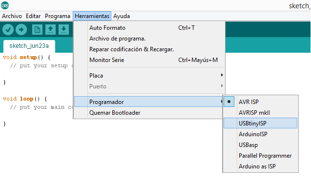
3. I clicked on Programmer -> USBtinyISP
6. I opened the Sublimetext file and changed the 0F for 14.
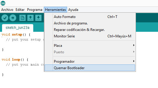
4. I tried to burn the Bootloader, but it did not work out...
.
5.
I initially chose an AVR mkii for programming my Fabduino, because I
thought it was going to be error-proof. However, I later realized an
AVR mkii's drivers, although installed, were not recognized neither by
my
computer nor other two students' computers. So, after a couple of
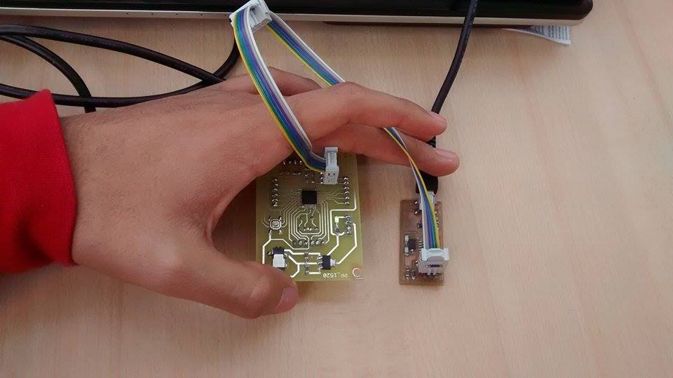
hours, Denis Chavarry borrowed me his Fab ISP that allowed me to burn
the Bootlander very easily. Here is the link that shows I burnt the Bootloader.
6. After burning the Bootloader, I changed the 14 for 0F again -> Tried Example -> Blink (for verfying its function).
Here is the link that shows my Fabduino working.
PROGRAMMING IN ARDUINO IDE
1.
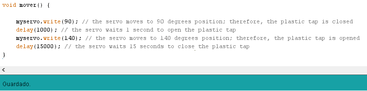
I developed my Arduino IDE program using Servo Sweep as a mold and then
modified it for developing a software that moves my servomotor to 90
degrees position (plastic tap is closed) to 140 degrees position
(plastic tap is opened) during 12 intervals.
You can download Servo Sweep program Here and my Valve2 program Here
2. My Arduino IDE program with each line explained by me, is shown below.
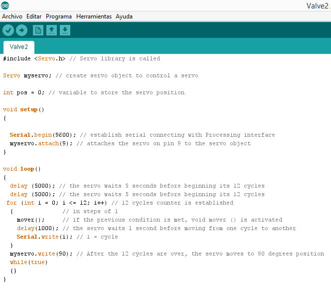
You can download Servo Sweep program Here and my Valve2 program Here
2. My Arduino IDE program with each line explained by me, is shown below.
3. While experimenting with Arduino, I discovered that void loop was an 'official' void,
but I need to add another one at the end of the program for changing
the servo position, because the void loop was just a counter (in this
case, a counter of times the Chicha is released).
PROGRAMMING IN PROCESING
1. I used Capture, available(), serialEvent() and read() as molds for developing the program that would allow my Webcam take a picture each time one of 12 Arduino cycles was over.
You can find Capture Here, available() Here, serialEvent() Here and read() Here. Also, here you can download my Processing program, FinalFotos.
2. My Processing program with each line explained by me, is shown below.
Here, in this video, my Automatic 3D Chicha scanner is fuly working.
ASSEMBLY
1. After cutting all the pieces in 6mm and 3mm acrylic, I assembled the third floor using cloroform and a ruler.
2. I assembled the second and first floor with the walls (in this order). I made the assembly using cloroform and a ruler.
3. I made sure that the third floor was going to fit with structure when joined by hinges.
4. I put my webcam, Fabduino and Servomotor in the Third Floor. I should said that I had to break the Servomotor acrylyc case, because I forgot to put it inside, before assembly. Anyway, I pasted it with cloroform and there was no toruble.
5. I tied the bronze elbow (next to my servomotor) to the Third Floor using a plastic belt. I pasted the bronze elbow with silicone.
6.
I pasted the battery case to an acrylyc wall, twisted a bottle in the
bronze elbow, put a bath tap in Second Floor hole, a 625ml bottle in
the First Floor and additional acrylic pieces at the bottom of the
First and Second Floor.
8. I connected the Servomotor's and Battery's cables to the Fabduino and the Processing did not work. Then, Eduardo Yallico told me, that as the Arduino was already feeding the Servomotor, it did not have voltage left to feed the Webcam (that's why my Laptop port was sound; it was opening anc closing). That's why I connected the Battery's VCC (red) cable to the Servomotor's VCC (red cable), the Battery's GND (black) cable and the Servomotor's GND (black) cable to the Fabduino and the Servomotor's Serial (yellow) cable to the Fabduino.
9. My project run successfully and this is how it looked.
You can download my video here.
10. I scanned the top of a Christmas Sugar Pot and a Sintestchotch. I should mention, that this process allowed me to realize experimentally that a plastic tap needs to remain open for 24 seconds, for getting the liquid height to increase 1cm. Here are the results of my experimentation:
11. The previous pictures can be joined using Photoshop or Rhinoceros. This would be the next step of my project. Here is a preview
What question needs to be resolved?
Is it possible to develop a software that generates a 3D Picture of an object just by uploading the pictures of the object's layers?
What will happen when?
I will develop the software mentioned above after I finish the Fab Academy.
BILL OF MATERIALS AND FUNCTIONS
1) 180cmx120cm 6mm Acrylic: It is the structure, where all the the project is supported
2) 20cmx20cm 3mm Acrylic: It is the adjustments material for efficient exit of Chicha, once the scanning its over.
3) FTDI Cable: It allows the Fabduino to receive the Arduino IDE Program and execute the Processing program.
4) [4] 1.5V Batteries Case: It supports 4 Batteries, and have 2 cables (GND and VCC) that connect with the Arduino board and the Servomotor.
5) [4] 1.5V Batteries: They provide energy to the system.
6) Half of Gatorade bottle: It works as a funnel that allows me to pour Chicha inside my machine
7) San Luis water bottle: It receives the Chicha when the scanning process is over. It helps the cleaning process.
8) Bath cap: It closes the Second Floor and allows to control the flow of Chicha.
9) Webcam: It takes pictures of each layer
10) Plastic tap: It allows the Chicha to get or not get inside the system
11) 15 kilograms Servomotor: It initializes or resets the plastic tap
12) 5cmx4cm Bronze elbow: It allows Chicha to get into the system without the need of an extra force, but gravity.
13) Plastic belt: It supports the elbow bronze
14) 1mm Nilon: It connects the Servomotor with the Plastic tap for creating the Open-Close tap mechanism
15) Terminal cables: They connect the Servomotor with the Battery and the Fabduino
16) Laptop: It allows me to program the Fabduino in Arduino and Processing.
17) Plastic Tube: It helps the Chicha get inside the system.
18) Pen cap: It allows the Chicha to exit slowly and carefully
19) Silicone: It fully closes the walls of the Second Floor
20) Scissors: It cuts Cables, Nilon and Plastic belt.
21) Ruler: It allows a more efficient wall-pasting.
22) Hinges and Screws: It connects the Structure with the Third Floor.
23) Cloroform and its needle: They are the liquid and tool that allow the pieces to join.
24) Fabduino: It is the piece that executes the orders in the entire system
- [3] 0.1uf Capacitors
- [2] 22pF Capacitors
- [2] 10uF Capacitors
- [2] LEDS
- [1] Jack. 65mm
- [1] 2x3 Pin
- [4] 1x6 Pins
- [1] 1x4 Pin
- [1] 10k Resistor
- [2] 499k Resistor
- [1] 0k Resistor
- 6mm Switch
- ATMega 328
- Regulator
- Crystal 22MHZ
25) 4,8 Liters of Chicha: It is input that allows the scanning process
26) Joining pictures software: It joins all the pictures for getting a 3D Image.
27) Scotch tape: For adhering the scanned object to the second floor surface
GENERAL CONCLUSIONS
What have you learned?
1. It is better to start first for the Electronics, because it is far easier for the Design to adapt to the Electronics than viceversa
2. When you need more than 5V for your system, you should connect sensors' VCC pins directly to the battery and sensor's GND pins directly to the Fabduino.
3. Some people in the Fab TECSUP mocked my project saying that it was a trash (maybe because it was rectangular and had a hole) or guided me through innecessarily complex routes (transistors, relays, electronic valves) for solving the servomtor-plastic tap mechanism. I learned not just to listen, but to evaluate the information, remaining in my two pillars: confidence and simplicity.