STEP 13: NETWORKING &COMMUNICATIONS
OBJECTIVE
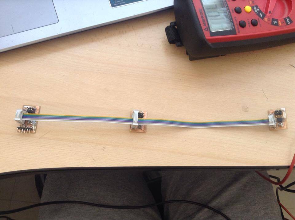
1. Network 3 boards through a serial bus connection
2. Create a Bridge Board and 2 Nodes
PROCEDURE
MILLING
1. Enter to Ubuntu and create a folder called Nodes in the Desktop.
2. Enter to Fab Academy Schedule 2015 and save the traces and interior of both hello.bus.45.bridge.cad and hello.bus.45.node.cad in Nodes
3. Mill 1 Bridge and Two Nodes in the Roland Modela
MODFYING PROGRAM
1. Enter to Fab Academy Schedule 2015 and save the hello.bus.45.c and makefile in Nodes.
2. Copy the hello.bus.45.c two times and change the files names to hello.bus2.45.c and hello.bus3.45.c
3. Because each Node needs to have its own ID number (0, 1, 2). It should be said, that a Bridge is essentially a Node with a FTDI header.
- Change #define node_id '0' for #define node_id '1' in hello.bus2.45.c and save it
- Change #define node_id '0' for #define node_id '2' in hello.bus3.45.c and save it
CONNECTING THE BOARDS
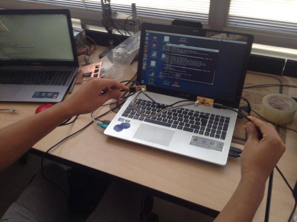
1. Connect the Bridge to the computer with a FTDI cable.
2. Identify the GND of the 2x3 pins of the Fab ISP using the board of the Electronics Production assignment-Week 4 and the boards of the Networking & Communications assignment-Week 13.
3. Identify the GND of the 2x3 pins of my Nodes using the Nodes' boards of the Networking & Communications assignment-Week 13.
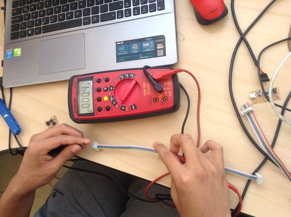
4. Use the Multimeter to identify which pin of the first board correspond to the second board in terms of current flow. Therefore, I put the Multimeter in current mode, put metal cables in each board's GND side of each end of the multicolour cable and touched each of them with the Multimeter. If there was a sound, there was current flow; otherwise I should change the position of one of the cable metals to the only hole left in one of the board's GND side.
5. I connected the Bridge with the FabISP meeting the correspondance requirement.
CHARGING PROGRAM
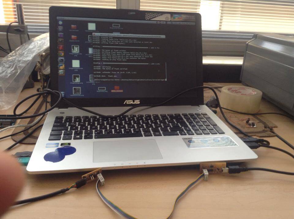
1. Open Ubuntu's Terminal
2. Write sudo bash and insert the computer's password
3. Write cd Desktop and click Enter
4. Write cd Nodes and click Enter.
5. Write sudo make -f hello.bus.45.make program-usbtiny. Click Enter
1. Network 3 boards through a serial bus connection
2. Create a Bridge Board and 2 Nodes
PROCEDURE
MILLING
1. Enter to Ubuntu and create a folder called Nodes in the Desktop.
2. Enter to Fab Academy Schedule 2015 and save the traces and interior of both hello.bus.45.bridge.cad and hello.bus.45.node.cad in Nodes
3. Mill 1 Bridge and Two Nodes in the Roland Modela
MODFYING PROGRAM
1. Enter to Fab Academy Schedule 2015 and save the hello.bus.45.c and makefile in Nodes.
2. Copy the hello.bus.45.c two times and change the files names to hello.bus2.45.c and hello.bus3.45.c
3. Because each Node needs to have its own ID number (0, 1, 2). It should be said, that a Bridge is essentially a Node with a FTDI header.
- Change #define node_id '0' for #define node_id '1' in hello.bus2.45.c and save it
- Change #define node_id '0' for #define node_id '2' in hello.bus3.45.c and save it
CONNECTING THE BOARDS
1. Connect the Bridge to the computer with a FTDI cable.
2. Identify the GND of the 2x3 pins of the Fab ISP using the board of the Electronics Production assignment-Week 4 and the boards of the Networking & Communications assignment-Week 13.
3. Identify the GND of the 2x3 pins of my Nodes using the Nodes' boards of the Networking & Communications assignment-Week 13.
4. Use the Multimeter to identify which pin of the first board correspond to the second board in terms of current flow. Therefore, I put the Multimeter in current mode, put metal cables in each board's GND side of each end of the multicolour cable and touched each of them with the Multimeter. If there was a sound, there was current flow; otherwise I should change the position of one of the cable metals to the only hole left in one of the board's GND side.
5. I connected the Bridge with the FabISP meeting the correspondance requirement.
CHARGING PROGRAM
1. Open Ubuntu's Terminal
2. Write sudo bash and insert the computer's password
3. Write cd Desktop and click Enter
4. Write cd Nodes and click Enter.
5. Write sudo make -f hello.bus.45.make program-usbtiny. Click Enter
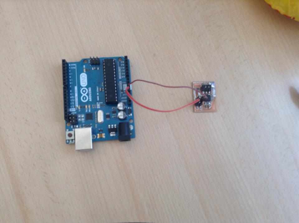
6. As my Nodes 1 and 2 do not have FTDI pins for receiving voltage from my computer,
I looked for a Battery. As I could not find one in the lab, I connected
the GND and VCC pins of my Nodes to its respective GND and VCC in an
Arduino UNO and connected it to my computer
7. I repeated the CONNECTING THE BOARDS and CHARGING PROGRAM (above) sections when charging the programs of the Node 1 and Node 2.
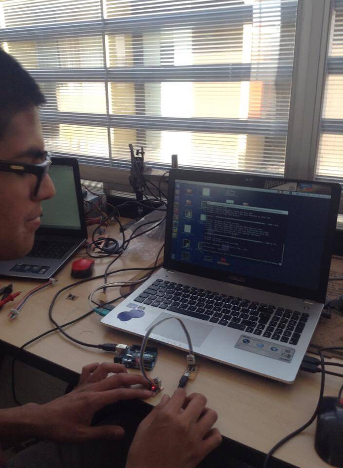

8. I added a new end (in the middle) to my Multicoulour cable. I followed ththe CONNECTING THE BOARDS section and connected the Bridge, and the Nodes using the correspondance rule.
9. Open Arduino IDE
10. I clicked on Tools -> Port -> COM6 (my case)
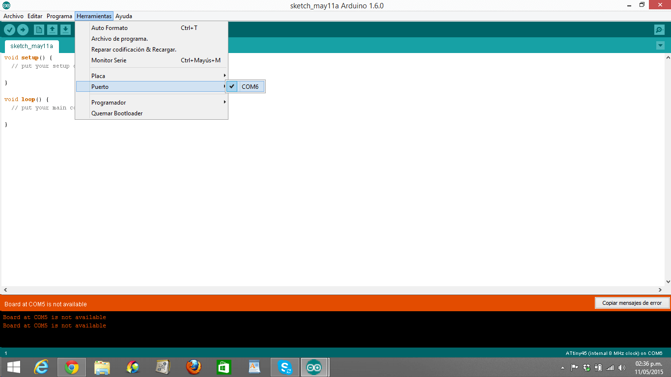
11. I clicked on Tools -> Serial Monitor
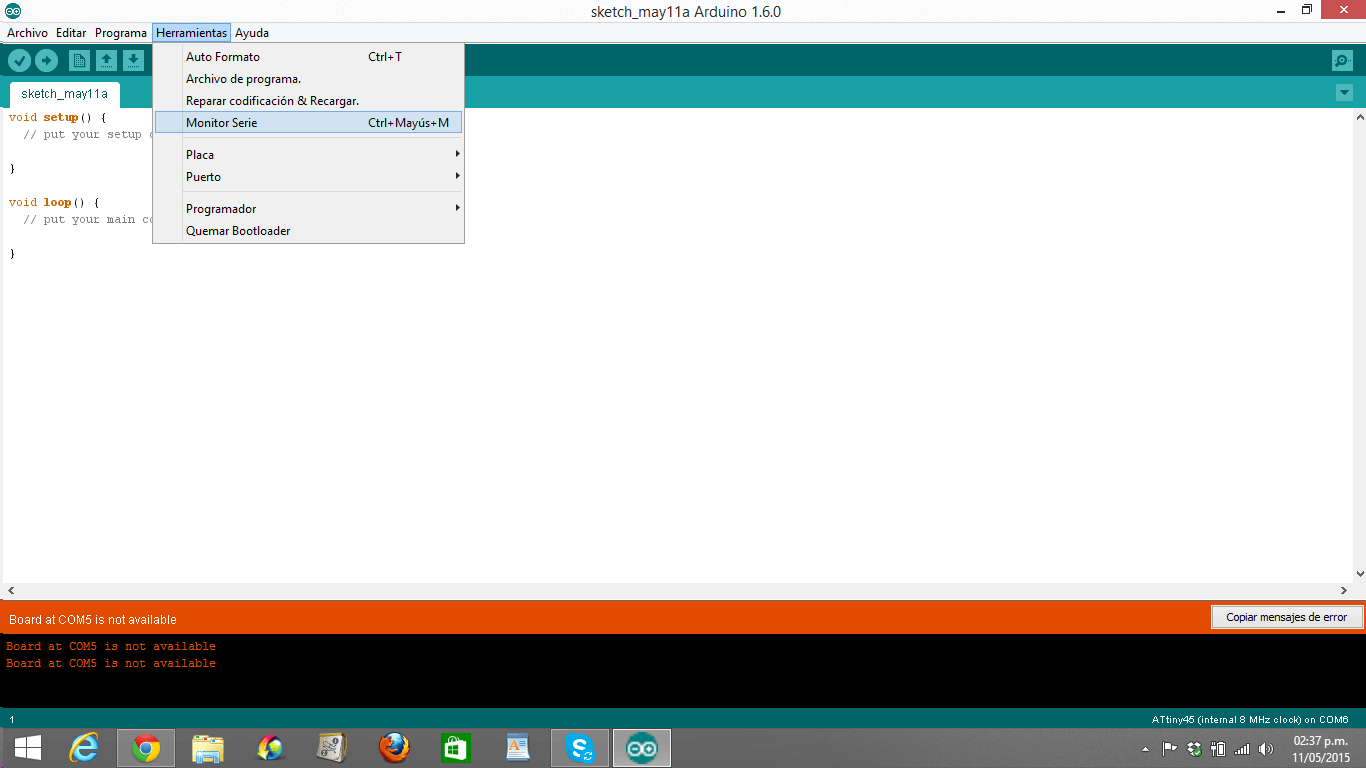
10. I clicked on Tools -> Port -> COM6 (my case)
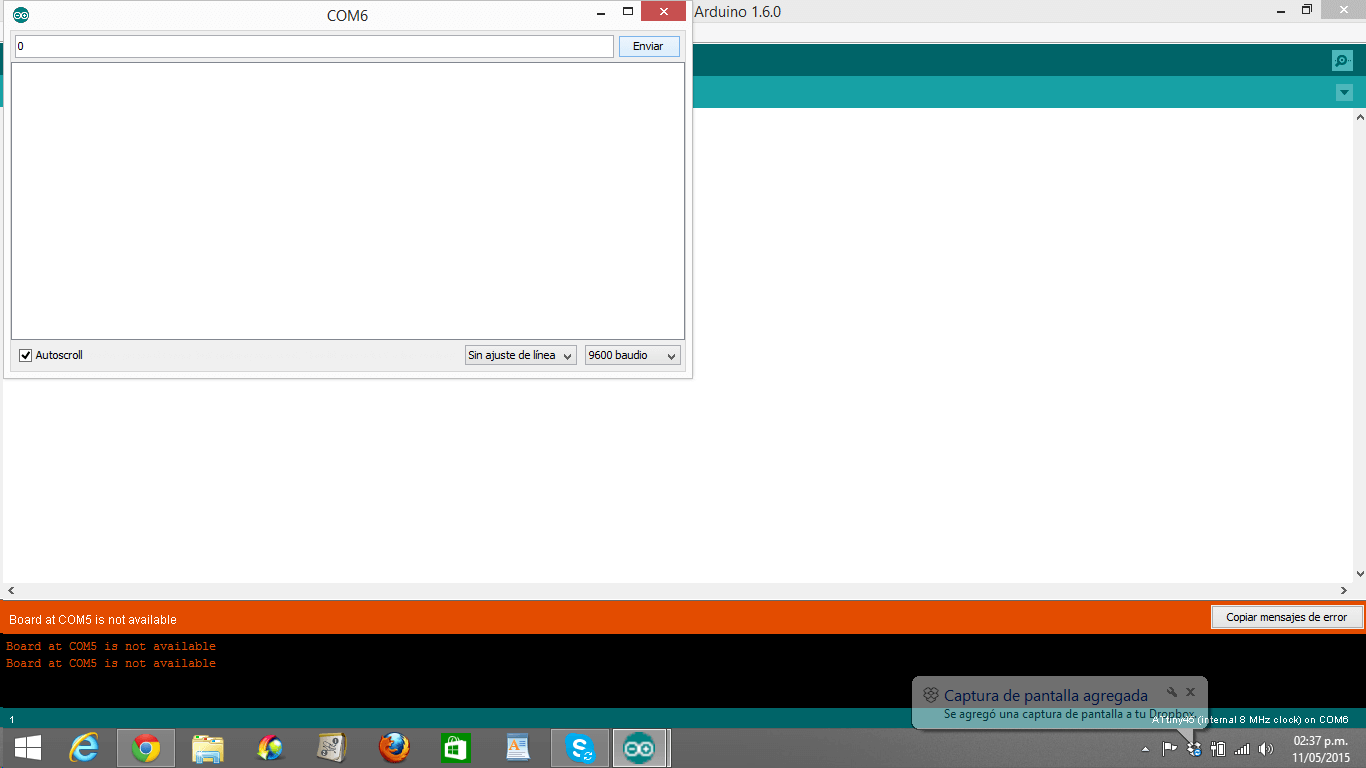
12. I made sure that the baud rate is 9600; otherwise, you will get random letters, numbers and symbols.
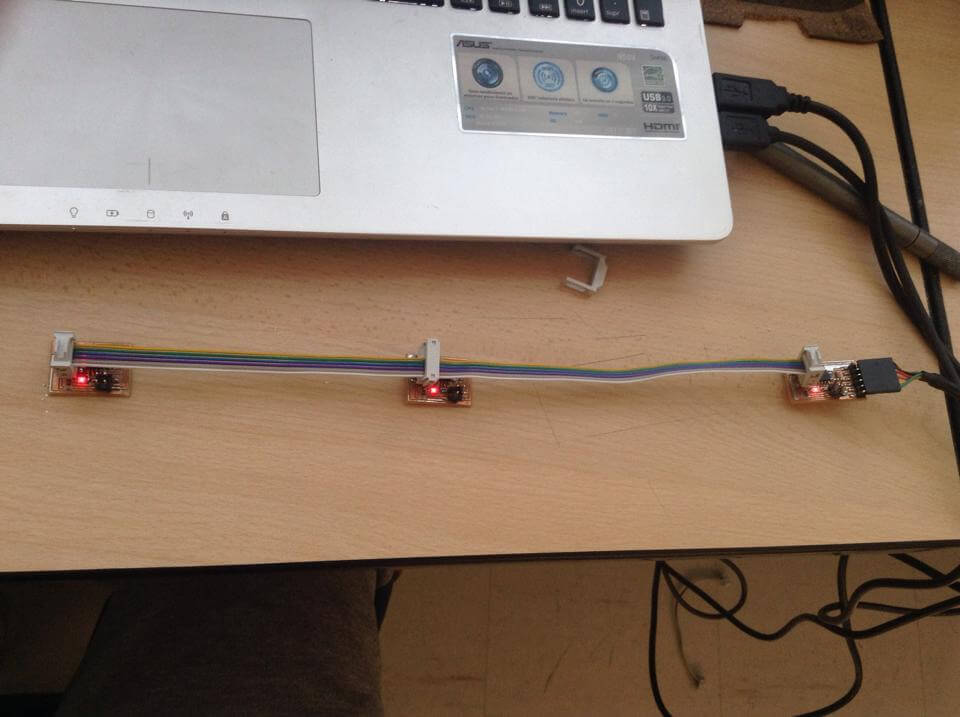
13. I picked '0', '1' and '2' numbers and clicked Send.
14. If my Bridge, Node 1 and Node 2 light up when I picked '0', '1' and '2' numbers, it means that my Bridge and my Nodes are working....and they are!
13. I picked '0', '1' and '2' numbers and clicked Send.
14. If my Bridge, Node 1 and Node 2 light up when I picked '0', '1' and '2' numbers, it means that my Bridge and my Nodes are working....and they are!
14. Here, is the video that proves that my Networking system works.
HOW NETWORKING WORKS? (PROTOCOL, WHAT I LEARNED)
From Neil's class
-Small processors (boards) do small tasks better and faster
- When the host transmits, everybody can listen to it, but respondingNOT (we have a porblem)
- Remember each of the pins can be high, low or disconnected
- I learned that in a NODE, Rx and Tx pins usually go this way:
1st pin = Rx
2nd pin = Tx
-
Normally if one wants to return information, one should change pins;
howeve, what Neil does, is to alternate the transmission and reception
order using the C program2nd pin = Tx